This thread has been locked.

If you have a related question, please click the "Ask a related question" button in the top right corner. The newly created question will be automatically linked to this question.

conflicting data sheet omapl137 in BOOT section

Other Parts Discussed in Thread: OMAPL137-HT, OMAPL138

Hi

We are using the data sheet that is specified for omapl137

The following is the conflict

omapl137-ht.pdf

spruh92c.pdf


I have attached the images for reference

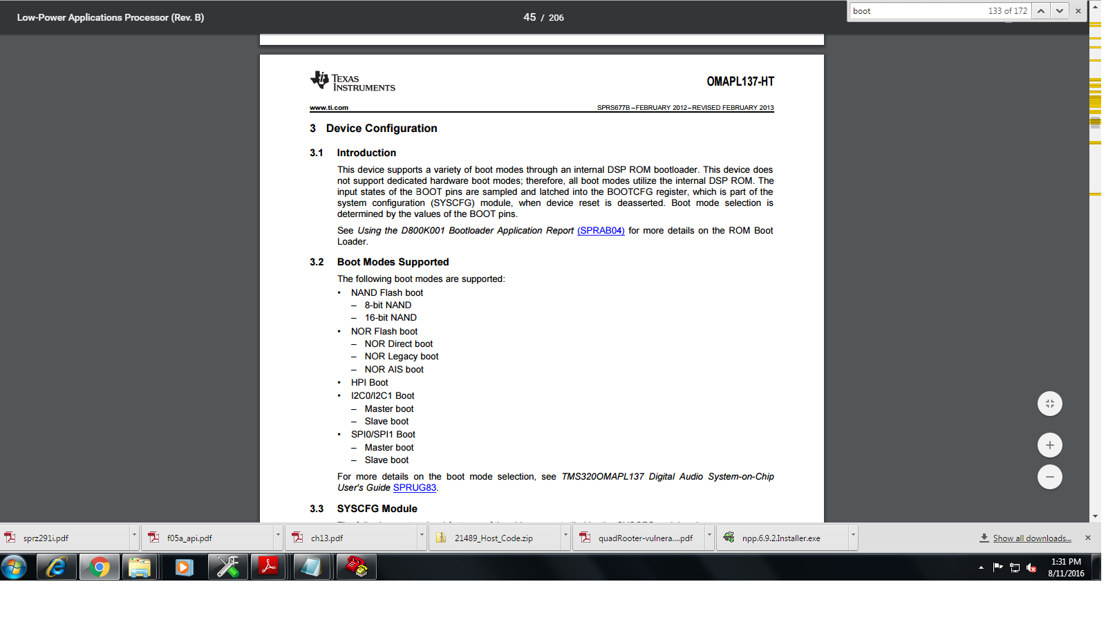
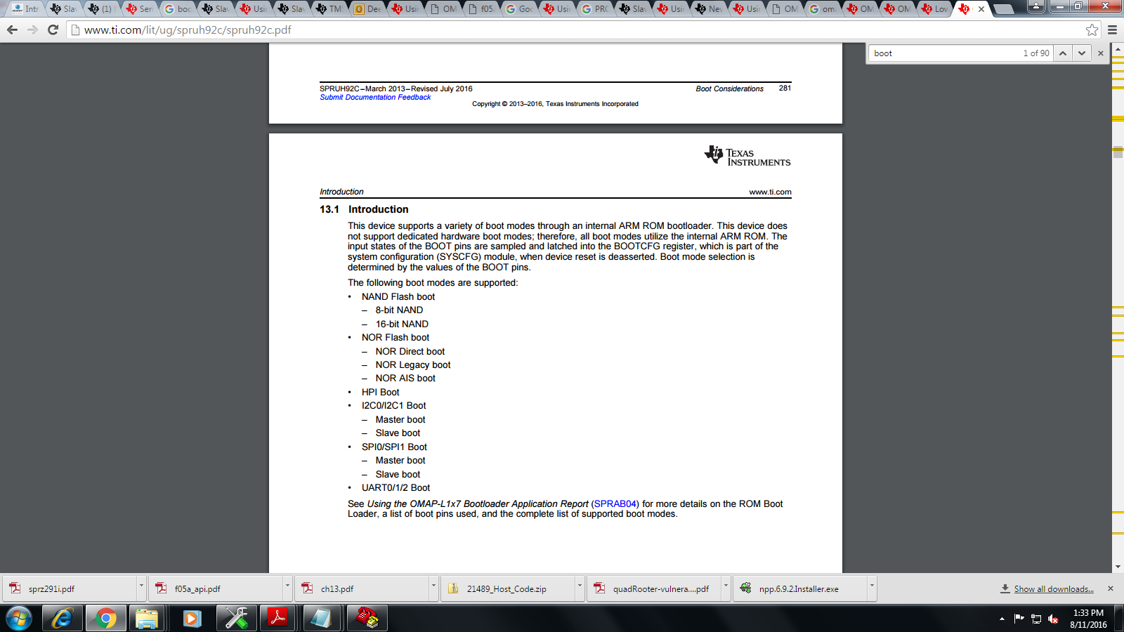
The following section IN DOCUMENT says the boot loader is taken from DSP ROM and ARM ROM

I have already a question regarding SLAVE BOOT spi0,

The OMAP we are using is OMAPL137BPTPH VERSION

I kindly request your team to respond on booting issue and clarify weather its booted from ARM or DSP BOOTLOADER and Refer an aprroach that should be followed w.r.t to booting the device from spi slave0 

Thank you

Deepak R 

  • Dear Deepak,
    OMAPL137 is DSP boot master device where as OMAPL138 is ARM boot master.
    In OMAPL137, DSP comes out from sleep after released the RESET and in OMAPL138 ARM comes out from sleep first then DSP.

    If you want to run any ARM application on OMAPL137 then you need to use DSP UBL code to wake the ARM core and run on it.
    In same way, you need to use ARM UBL to wakeup the DSP and run the DSP app on OMAPL138 device.

    You can run DSP app directly on OMAPL137 and ARM app on OMAPL138.

    If you want to do slave boot in OMAPL137 then code should run on DSP core (need to develop code with DSP).

    Please let me know if any understanding issue on this.
  • Hi

    Titu

    Thanks for responding!

    My question regarding slave boot is  that

    I have a master as (i.e MCUSM470 ) and slave as DSP OMAPL137

    I have followed the approach of implementing the protocol as specified in the boot document

    Start-word synchronization (SWS),

    Ping Op-code synchronization (POS) and

    Op-code synchronization (OS).

    Needs to be implemented

    I have a Mcu controller that acts as a Master(MCUSM470RIBIM)  & DSP OMAPL137

    Dsp is selected to boot from spi slave 0 and corresponding pins on the line is set accordingly

    On the Mcu side our application tries to communicate with ,HERE (on MCU SPI2) that is connected to SPI0 SLAVE ON DSP

    The clock frequency of spiclock on MCU is 1 MHZ    

    the following is the implementation done on MCU side to send the XMT_START and recieve RCV_START

    ///////////////////////////
    
    #define XMT_START_H 0X5853   ----->opcode to send start transfer
    
    #define RECV_START     0X5253  ----->opcode received Ack  
    
    while(1)
    
    {
    
    for(x=0;x<1;x++) // TRYING TO TRANSFER ONCE
    
    {
    
    sleep(400000);  //THIS PROVIDES A DELAY OF 2SEC i am changing the delays and checking for 50usec to 1sec between each command processing
    
    sws_value = sws_synchronisaton_spi2(0x5853);  TRYING TO WRITE THE VALUE OF XMT_START
    
    send_int(sws_value);// PRINT THE VALUE ON CONSOLE
    
    }
    
    if(sws_value == RECV_START)
    
    {
    
    break;
    
    }
    
    for(x=0;x<1;x++)
    
    {
    
    sleep(200000);
    
    sws_value = sws_synchronisaton_spi2(0xFFFF);   /// TRYING TO READ BACK IF DATA IS PRESENT BY WRITING FFFF SO THAT IT DOESENT STARTING PROCESSING AGAIN THINKING ITS 0X5853
    
    send_int(sws_value);
    
    }
    
    if(sws_value == RECV_START)
    
    {
    
    break;
    
    }
    
    sleep(200);
    
    }
    
    //////////////////////////
    
    int sws_synchronisaton_spi2(unsigned short cmd_data)
    
    {
    
    int val;
    
    int i;
    
    unsigned short data = 0;
    
    //------------------------------------------------------------------------------------
    
    SPI2PC3 &= 0xFFEF; // CS Pin is made LOW
    
    for(i=0;i<1;i++)
    
    {
    
    SPI2DAT1 = cmd_data; // This is just a dummy read. No affect on this
    
    sleep(5);
    
    }
    
    // SPI2PC3 |= 0x0010; // CS Pin is made HIGH*/
    
    // sleep(5);
    
    //------------------------------------------------------------------------------------*/
    
    //--------------------------------------------------------------------------------------
    
    // SPI2PC3 &= 0xFFEF; // CS Pin is made LOW
    
    sleep(5);
    
    while(!(SPI2CTRL3_bit.RXINTFLAG & 0x1));
    
    data = SPI2BUF;
    
    sleep(50);
    
    SPI2PC3 |= 0x0010; // CS Pin is made HIGH
    
    return data;
    
    }

    I am changing the delays and checking for 50usec to 1sec between each command processing

    I have searched different forums and different approach for sending the command 0x5853 IN FOR AND WHILE LOOP and receiving I always end up in 0XFFFF

     Here i am trying to send the the XMT_START 0X5853 which has to be transmitted and receive  RECV_START 0x5253

    I am able to send the data on the MOSI line (MASTER OUT SLAVE IN)  and the proper value appears on CRO but I am not able to get back any response

    from the DSP it always gives 0XFFFF as output .

    I have also refereed to the atuil.cs file that does   the uART  transmission,

    What could be the proper approach ?

    Where could i be going wrong??

    KINDLY SUGGEST  I HAVE CHECK THE BOOTCONF PIN ALSO AND HOST1CFG THOSE VALUES ARE SET ACCORDINGLY

    Thank you

    Deepak R