This thread has been locked.

If you have a related question, please click the "Ask a related question" button in the top right corner. The newly created question will be automatically linked to this question.

Inrush current to TSC ADC pin of AM335x

Hi,

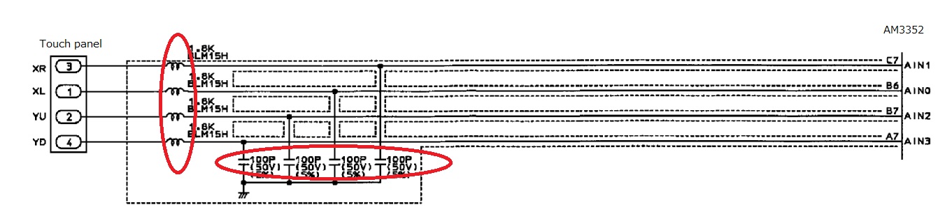
By noise measures, our customer added a condenser (4,700pF) to the line of the touch panel, but an inrush current in this way becomes about 150mA/100nsec.
With the data sheet of AM335x, the drive current of the TSC ADC lists it with up to 25mA.

TSC ADC pin flows through about 150mA/100nsec by an inrush current, will there be a problem?

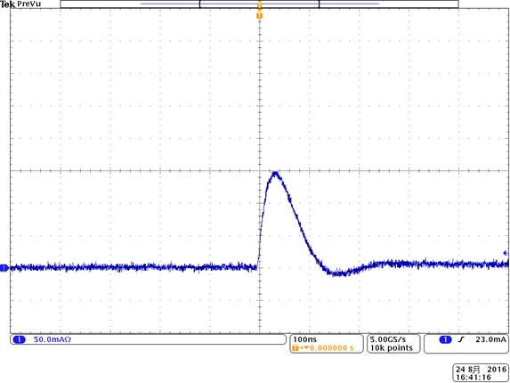
The following inrush current is input.

Best Regards,
Shigehiro Tsuda

  • Hi,

    I will ask the factory team to comment.
  • Meanwhile could you explain how your customer uses the ADC? Are they connecting it to a resistive touch screen? If so, I would have expected the touch response to be very slow with this size capacitor connected to the touch screen signals. The RC time constant would make the response very slow.
  • Hi Biser,

    Thank you for quick reply.
    Our customer are connecting it to a resistive touch screen.
    The response of the touch does not seem to have any problem.

    There is a question from our customer by addition.
    About the inrush current to TSC ADC pin, how much is the permissible maximum?

    Best Regards,
    Shigehiro Tsuda
  • This peak current is not compliant to the specification and has not been characterized. Please ask the customer to insert a small value resistor, about 27 ohms, between each AIN pin and the capacitor. Hopefully this will reduce the inrush current to an acceptable level without degrading touch screen performance.

    Regards,
    Paul
  • Hi Paul,

    Thank you for quick reply.

    I confirm whether a noise is reduced by your doing a suggested method to our customer.

    Please wait about the result.

    Best Regards,
    Shigehiro Tsuda

  • Hi Paul,

    Our customer added resistance of 27ohms, but did not seem to be able to reduce the noise.

    They added a coil, resistance any place other than capacitor and confirmed it, but were not effective.

    About the fixed number of capacitor, they put 100PF and chose 100PF → 4700PF so that an uptake wave pattern of the touch panel does not have influence, but the concern of the inrush current has been left.

    It does not seem to be digitized about a peak current, 
    can you not determine whether there is a problem in about 150mA/100nsec?

    Best Regards,
    Shigehiro Tsuda

  • I would like to confirm how they connected the 4700pf capacitor to reduce noise.

    I assume they connected one terminal of a 4700pf capacitor to each AIN pin connected to the resistive touch screen. The other terminal of each capacitor is connected to ground, and they are positioned near the AIN pin. Is this correct?

    If so, these capacitors will shunt any noise coupled into the touchscreen and associated signals to ground.

    When the touch screen controller provides power to the resistive planes, the capacitors would need to be charged. This produces a large inrush current because there is nothing to limit the current. The peak current would be reduced by inserted 27 ohm resistors between the AIN pins and capacitors since the series resistor limits inrush current required to charge the capacitor.

    Assuming the capacitors are still connected to the touch screen signals near the AIN pins, they would still shunt any noise to ground. The series resistors should not have any effect on noise immunity. However, they would reduce the inrush current.

    Regards,
    Paul
  • Hi Paul,

    Thank you for quick reply.

    Our customer seems to be connected like the following figure.
    Even if this inductor changes it to the resistance, there is no effect.

    According to your answer, must our customer attach resistance between AIN pin and capacitor?
    In the case of this workaround, it is told that there is not it because a circuit change is necessary from our customer.
    Is there other workaround?

    Best Regards,
    Shigehiro Tsuda

  • As mentioned previously, they should insert 27 ohm resistors between the capacitors and the AIN terminals. Inserting them between the capacitors and touch screen will not reduce the inrush current.

    Regards,
    Paul

  • I'm not aware of any way to keep the shunt capacitance on the touch screen signals and reduce the inrush current from the AIN terminals without changing the PCB design.

    Regards,
    Paul
  • Hi Paul,

    Thank you for quick reply.

    I will confirm whether they can insert 27ohms resistance between capacitor and AIN pin again.
    Thank you for your quick and kind support.

    Best Regards,
    Shigehiro Tsuda

  • Hi Paul,

    I recommended addition of 27ohms to our customer, but it was result that they could not modify their PCB because their product had been already mass-produced.

    Plese tell me the following.
    1.Can their inrush current not permit specifications of AIN pin?
    2.When they continue using it without 27ohms, what kind of risk occurs?

    Best Regards,
    Shigehiro Tsuda

  • It is not recommended to operate the device outside limits defined in the data sheet. However, we cannot prevent them from using the device this way.

    We are not able to say for certain what will happen since device performance was only evaluated for operating within the limits defined in the data sheet. Electromigration is one example of a failure mechanism that could occur when operating semiconductors at high than expected currents.

    Regards,
    Paul

  • Hi Paul,

    Thank you for quick reply.
    I think that the data sheet of AM335x is not defined specification of AIN input current.
    Do you mean MAX value(25mA) of drive current with mention in "Table 5-16 TSC_ADC Electrical Parameters"?
    Please tell me about the reason that you regard as a problem.

    Best Regards,
    Shigehiro Tsuda
  • If you look at the Analog Front End (AFE) Functional Block Diagram in Figure 12-2 of the AM335x TRM, you will see output transistors connected to terminals AIN[4:0]. The touch screen controller will turn on the appropriate transistor as required to connect VDDA and VSSA to the resistive panel. These output transistors will charge/discharge any shunt capacitance connected to the AIN terminals. The transistors are large and capable of sourcing large amounts of current. In the example mention in my previous post, the internal metal paths that connect the transistors to the AIN pin may be compromised by electromigration effects if the customer exceeds the maximum current defined in the data sheet.

    There are other potential issues. For example, the large peak currents can also cause significant voltage transients in the power supply and may produce enough noise that it couples into other circuits.

    Regards,
    Paul
  • Hi Paul,

    Thank you for quick reply.
    I understood almost by your detailed explanation.

    But I do not understand follows in your answer.
    Please tell me where of the data sheet "the maximum current defined in the data sheet" shows.

    Best Regards,
    Shigehiro Tsuda

  • It is on page 96 of the AM335x data sheet (SPRS717J –OCTOBER 2011–REVISED APRIL 2016), third from last parameter in Table 5-16.

    Regards,
    Paul
  • Hi Paul,

    Thank you for quick reply.
    Is it Drive current(max 25mA) of Table 5-16?

    Best Regards,
    Shigehiro Tsuda
  • Hi Paul,

    Thank you for quick reply.

    I understood it.
    Thank you for your kindly and quick support.

    Best Regards,
    Shigehiro Tsuda