This thread has been locked.

If you have a related question, please click the "Ask a related question" button in the top right corner. The newly created question will be automatically linked to this question.

SYS/BIOS project boot problem over PCIe from MSMCSRAM for EVMC6678

Other Parts Discussed in Thread: SYSBIOS

Hello guys !

I can succesfully use DSP projects with BIOS or without BIOS when booting it with a help of 560v2 emulator. I am also able to boot my specific DSP project without BIOS and without any code optimizations over PCIe with a help of linux host bootloader, which is in \ti\mcsdk_2_01_02_06\tools\boot_loader\examples\pcie\linux_host_loader folder. I didn't modify the process of pushing DSP code from host side. When I don't have BIOS in my project and don't use any code optimizations for speed all the sections fit well inside LL2 memory and project is succesfully booted over PCIe and works in the way I expect.

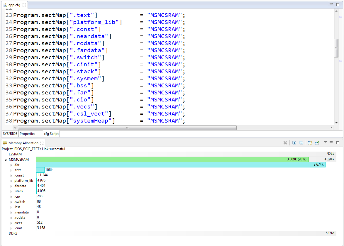
Now I would like to pcie boot project which uses BIOS and which is optimized for speed. I have made such project and checked that it works succesfully when I load it via 560v2. Because of BIOS and speed optimizations more space was required and thats why I put all the code into MSMCSRAM, which fits my purposes well - is fast and will be available for all cores.  Here is my memory map from BIOS .cfg file:

Program.sectMap[".data"] 			= "MSMCSRAM";
Program.sectMap[".csl_vect"] 		= "MSMCSRAM";
Program.sectMap[".text"] 			= "MSMCSRAM";
Program.sectMap["platform_lib"] 	= "MSMCSRAM";
Program.sectMap[".const"] 			= "MSMCSRAM";
Program.sectMap[".neardata"] 		= "MSMCSRAM";
Program.sectMap[".rodata"] 		    = "MSMCSRAM";
Program.sectMap[".fatdata"] 		= "MSMCSRAM";
Program.sectMap[".switch"] 			= "MSMCSRAM";
Program.sectMap[".cinit"] 			= "MSMCSRAM";
Program.sectMap[".stack"] 			= "MSMCSRAM";
Program.sectMap[".sysmem"] 			= "MSMCSRAM";
Program.sectMap[".bss"] 			= "MSMCSRAM";
Program.sectMap[".far"] 			= "MSMCSRAM";
Program.sectMap[".cio"] 			= "MSMCSRAM";

I have succesfully converted the out file to .h file with a help of helloworld_elf2HBin.bat. The projected is booted, BIOS starts (I suppose that is does, because I programmed the LED to blink in IDLE thread), but nothing more works in the project - no interrupts, no math, no data transactions over PCIE. Probably I have the same problem which was discussed in this thread: https://e2e.ti.com/support/dsp/c6000_multi-core_dsps/f/639/t/136505  not all the sections are loaded, but not sure. Also maybe I am doing something wrong in DSP boot sequence: first EVM init + interrupt configuration via CSL, than from main: bios_start and start_boot.

Does anyone know how can I solve such problem ?

  • Hi Ivan,

    I've notified the PCIe experts. Their feedback will be posted here.

    Best Regards,
    Yordan
  • Ivan,

    The Helloworld PCIE boot has two stages:

    • load code into L2 to initialize DDR
    • load helloworld code into DDR to have all cores booting from there

    As you you are booting from MSMC, if you change your code into DDR instead of MSMC, will it work (I guess not)? Also, even the common code can be placed into DDR or MSMC, for individual cores, the stack, sysmem ... are still placed into LL2, such as below:

    SECTIONS
    {
      .text > DDR
      platform_lib > DDR
      .const > DDR
      .neardata > LL2
      .fardata > DDR
      .switch > DDR
      .cinit > DDR
      .stack > LL2
      .sysmem > LL2
      .bss > LL2
      .far > LL2
      .cio > LL2
    }

    Can you use the same method in your SYSBIOS project?

    Regards, Eric

  • Hello, Iding!

    Thank you for your answer.

    No I can't do that because I can't fit my sections into L2 cache. In my project I have to dynamically allocate large ammount of memory in order to store data vectors there, that's why I have large stack section, I also have bios and speed optimizations and so on... I suppose that MSMCSRAM is not the best place to do that, but it is faster than DDR3 and fits my purposes right now as a temprorary test variant. 

    Here is the memory map of my NON BIOS project (from .cmd file), which does almost the same what BIOS project does, but without optimizations and memory allocations.

    In main I do the following:

    main()
    {
     platform init + memory init;
     CIC configurations;
     start_boot();
    }

    Here is the memory map of my BIOS project (from .cfg) file and memory allocation graph:

    In main I do the following:

    main()
    {
     platform init + memory init (in init BIOS block);
     CIC configurations via BIOS API;
     BIOS_start();
     start_boot();
    }

    For NON BIOS project everything works fine (when I load project with a help of XDS debugger and when my linux host boots it via PCIE);

    For BIOS project it works only when I load it via debugger. Under PCIE boot I can see that BIOS starts and the idle thread starts to work ( I just blink LED).

    Here is the output of hex6x utility for both BIOS and NON-BIOS project:

    Because BIOS starts I think that maybe some sections are not converted with this tool, and found some forum posts about that also, but didn't find the solution there. As far as I understood sections which have to be converted depend on the .rmd file somehow. I tried to put there SECTIONS by myself, it works , but doesn't give result. 

    Here is the .rmd file which I use with utility for both projects:

    -a
    -boot
    -e _c_int00
    
    ROMS
    {
    	ROM1:  org = 0x80000000, length = 0x200000, memwidth = 32, romwidth = 32     
    	files = { pcieboot.btbl }
    }

    Hard to understand how this .rmd influence the final header which I receive after hfile2array and Bttbl2Hfile convertion even when I have read spru186w document about hex6x, ROMs and so on.

    Maybe I don't understand the whole procedure of convertion or miss something in project logic itself. 

  • Still searching for the answer and would be very grateful for the advice)