Hello Titus and Shankari,
I have been trying to run U-boot but I haven't had success.
First of all, my board has the following hardware:
SPI Flash : K0XMFI011 (Spansion) - 4MBytes - Connected to SPI0
Nand Flash: S34ML01G200TFI000 (Spansion) - 128MBytes - Connected to EMIFA
SDR SDRAM : AS4C16M16SA (Alliance Memory) - 32MBytes - Connected to EMIFB - Only one RAM chip
Ethernet : LAN8720a
Audio : TLV320AIC3106
Power : TPS65023
Important : I need UART1 to be used for the console. This is for U-boot and Linux as well.
I understand that for changing the port from UART2 to UART1 I need to change some files. After lots of search I arrived at some instructions:
https://e2e.ti.com/support/dsp/omap_applications_processors/f/42/p/343979/1202078
https://e2e.ti.com/support/embedded/linux/f/354/t/155860#pi317016=1
Those instructions are for OMAP-L138, however I thought that similar instructions could apply to the AM1705 as well, so I tried to merge them.
I'm using DaVinci-PSP-SDK-03.20.00.14.
The U-boot directory is: DaVinci-PSP-SDK-03.20.00.14-custom/src/u-boot/uboot-03.20.00.14/
I did the following:
1) In file “include/asm-arm/arch-davinci/hardware.h”
/* Emulation suspend bits */
#define DAVINCI_SYSCFG_SUSPSRC_EMAC (1 << 5)
#define DAVINCI_SYSCFG_SUSPSRC_I2C (1 << 16)
#define DAVINCI_SYSCFG_SUSPSRC_SPI0 (1 << 21)
#define DAVINCI_SYSCFG_SUSPSRC_SPI1 (1 << 22)
#define DAVINCI_SYSCFG_SUSPSRC_UART2 (1 << 20)
#define DAVINCI_SYSCFG_SUSPSRC_UART1 (1 << 19) //Added this one
#define DAVINCI_SYSCFG_SUSPSRC_TIMER0 (1 << 27)
2) In file “include/configs/da830evm.h:”
-Mod1: Changed DAVINCI_UART2_BASE to DAVINCI_UART1_BASE
/*
* Serial Driver info
*/
#define CONFIG_SYS_NS16550
#define CONFIG_SYS_NS16550_SERIAL
#define CONFIG_SYS_NS16550_REG_SIZE -4 /* NS16550 register size */
#define CONFIG_SYS_NS16550_COM1 DAVINCI_UART1_BASE /* Base address of UART1 */
#define CONFIG_SYS_NS16550_CLK clk_get(DAVINCI_UART2_CLKID)
#define CONFIG_CONS_INDEX 1 /* use UART0 for console */
#define CONFIG_BAUDRATE 115200 /* Default baud rate */
#define CONFIG_SYS_BAUDRATE_TABLE { 9600, 19200, 38400, 57600, 115200 }
-Mod2: Changed SDRAM memory size from 64Mbytes to 32Mbytes
/*
* Memory Info
*/
#define CONFIG_SYS_MALLOC_LEN (0x10000 + 1*1024*1024) /* malloc() len */
#define CONFIG_SYS_GBL_DATA_SIZE 128 /* reserved for initial data */
#define PHYS_SDRAM_1 DAVINCI_DDR_EMIF_DATA_BASE /* DDR Start */
#define PHYS_SDRAM_1_SIZE (32 << 20) /* SDRAM size 32MB */
#define CONFIG_SYS_MEMTEST_START PHYS_SDRAM_1 + 0x2000000 /* memtest start addr */
#define CONFIG_SYS_MEMTEST_END (PHYS_SDRAM_1 + 0x2000000 + 16*1024*1024) /* 16MB test */
#define CONFIG_NR_DRAM_BANKS 1 /* we have 1 bank of DRAM */
#define CONFIG_STACKSIZE (256*1024) /* regular stack */
3) In file “board/davinci/da8xxevm/da830evm.c”:
-Mod1: Changed pinmux settings from UART2 to UART1
/* UART pin muxer settings */
const struct pinmux_config uart_pins[] = {
{ pinmux[11], 1, 2 },
{ pinmux[11], 1, 3 }
};
-Mod2: Changed DAVINCI_LPSC_UART2 to DAVINCI_LPSC_UART1:
/*
* Power on required peripherals
* ARM does not have access by default to PSC0 and PSC1
* assuming here that the DSP bootloader has set the IOPU
* such that PSC access is available to ARM
*/
lpsc_on(DAVINCI_LPSC_AEMIF); /* NAND, NOR */
lpsc_on(DAVINCI_LPSC_SPI0); /* Serial Flash */
lpsc_on(DAVINCI_LPSC_EMAC); /* image download */
lpsc_on(DAVINCI_LPSC_UART1); /* console */
lpsc_on(DAVINCI_LPSC_GPIO);
-Mod3: Changed DAVINCI_SYSCFG_SUSPSRC_UART2 to DAVINCI_SYSCFG_SUSPSRC_UART1:
/* setup the SUSPSRC for ARM to control emulation suspend */
writel(readl(&davinci_syscfg_regs->suspsrc) &
~(DAVINCI_SYSCFG_SUSPSRC_EMAC | DAVINCI_SYSCFG_SUSPSRC_I2C |
DAVINCI_SYSCFG_SUSPSRC_SPI0 | DAVINCI_SYSCFG_SUSPSRC_TIMER0 |
DAVINCI_SYSCFG_SUSPSRC_UART1),
&davinci_syscfg_regs->suspsrc);
-Mod4: Changed davinci_uart2_ctrl_regs to davinci_uart1_ctrl_regs:
/* enable the console UART */
writel((DAVINCI_UART_PWREMU_MGMT_FREE | DAVINCI_UART_PWREMU_MGMT_URRST |
DAVINCI_UART_PWREMU_MGMT_UTRST),
&davinci_uart1_ctrl_regs->pwremu_mgmt);
4) Again in file “include/configs/da830evm.h:”
-Mod1: Changed the following line for LAN8720A
/*
* Network & Ethernet Configuration
*/
#define CONFIG_DRIVER_TI_EMAC
#ifdef CONFIG_DRIVER_TI_EMAC
#undef CONFIG_MII
#define CONFIG_DRIVER_TI_EMAC_USE_RMII
#define CONFIG_BOOTP_DEFAULT
#define CONFIG_BOOTP_DNS
#define CONFIG_BOOTP_DNS2
#define CONFIG_BOOTP_SEND_HOSTNAME
#define CONFIG_NET_RETRY_COUNT 10
#define CONFIG_NET_MULTI
#endif
After saving all the files, I compiled successfully by using:
make distclean CROSS_COMPILE=arm-none-linux-gnueabi-
make da830evm_config CROSS_COMPILE=arm-none-linux-gnueabi-
make all CROSS_COMPILE=arm-none-linux-gnueabi-
The result for this operation were 2 files: u-boot and u-boot.bin
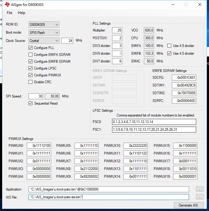
Then using AISgen for D800K005 and the u-boot.bin image I created an AIS image. The settings are the following:
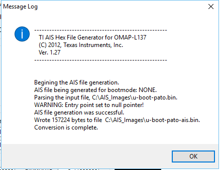
The message log was the following:
There is a WARNING: Entry point set to null pointer!
Is this a problem?
Once having the AIS file I did the following in a command window under Windows
1) I erased the SPI flash:
C:\AIS_Images>sfh_OMAP-L137.exe -targetType AM1707 -erase -p "COM6"
-----------------------------------------------------
TI Serial Flasher Host Program for OMAP-L137
(C) 2016, Texas Instruments, Inc.
Ver. 1.67
-----------------------------------------------------
[TYPE] Global erase
[TARGET] AM1707
[DEVICE] SPI_MEM
[SPI Block] 0
Attempting to connect to device COM6...
Press any key to end this program at any time.
(AIS Parse): Read magic word 0x41504954.
(AIS Parse): Waiting for BOOTME... (power on or reset target now)
(AIS Parse): BOOTME received!
(AIS Parse): Performing Start-Word Sync...
(AIS Parse): Performing Ping Opcode Sync...
(AIS Parse): Processing command 0: 0x58535901.
(AIS Parse): Performing Opcode Sync...
(AIS Parse): Loading section...
(AIS Parse): Loaded 7968-Byte section to address 0x80000000.
(AIS Parse): Processing command 1: 0x58535901.
(AIS Parse): Performing Opcode Sync...
(AIS Parse): Loading section...
(AIS Parse): Loaded 124-Byte section to address 0x80001F20.
(AIS Parse): Processing command 2: 0x58535901.
(AIS Parse): Performing Opcode Sync...
(AIS Parse): Loading section...
(AIS Parse): Loaded 748-Byte section to address 0x80001F9C.
(AIS Parse): Processing command 3: 0x58535906.
(AIS Parse): Performing Opcode Sync...
(AIS Parse): Performing jump and close...
(AIS Parse): AIS complete. Jump to address 0x80000000.
(AIS Parse): Waiting for DONE...
(AIS Parse): Boot completed successfully.
Waiting for SFT on the OMAP-L137...
Erasing flash
100% [ ████████████████████████████████████████████████████████████ ]
Erase complete
Operation completed successfully.
2) Flashed u-boot-pato-ais.bin to the SPI flash:
C:\AIS_Images>sfh_OMAP-L137.exe -targetType AM1707 -flash_noubl -v -p "COM6" u-boot-pato-ais.bin
-----------------------------------------------------
TI Serial Flasher Host Program for OMAP-L137
(C) 2016, Texas Instruments, Inc.
Ver. 1.67
-----------------------------------------------------
[TYPE] Single boot image
[BOOT IMAGE] u-boot-pato-ais.bin
[TARGET] AM1707
[DEVICE] SPI_MEM
[SPI Block] 0
Attempting to connect to device COM6...
Press any key to end this program at any time.
(AIS Parse): Read magic word 0x41504954.
(AIS Parse): Waiting for BOOTME... (power on or reset target now)
(AIS Parse): BOOTME received!
(AIS Parse): Performing Start-Word Sync...
(AIS Parse): Performing Ping Opcode Sync...
(AIS Parse): Processing command 0: 0x58535901.
(AIS Parse): Performing Opcode Sync...
(AIS Parse): Loading section...
(AIS Parse): Loaded 7968-Byte section to address 0x80000000.
(AIS Parse): Processing command 1: 0x58535901.
(AIS Parse): Performing Opcode Sync...
(AIS Parse): Loading section...
(AIS Parse): Loaded 124-Byte section to address 0x80001F20.
(AIS Parse): Processing command 2: 0x58535901.
(AIS Parse): Performing Opcode Sync...
(AIS Parse): Loading section...
(AIS Parse): Loaded 748-Byte section to address 0x80001F9C.
(AIS Parse): Processing command 3: 0x58535906.
(AIS Parse): Performing Opcode Sync...
(AIS Parse): Performing jump and close...
(AIS Parse): AIS complete. Jump to address 0x80000000.
(AIS Parse): Waiting for DONE...
(AIS Parse): Boot completed successfully.
Waiting for SFT on the OMAP-L137...
Target: BOOTUBL
Target: DONE
Flashing application u-boot-pato-ais.bin (157224 bytes)
Target: INFO: SPI Memory Initialization passed.
Target: SENDIMG
Target: BEGIN
100% [ ████████████████████████████████████████████████████████████ ]
Image data transmitted over UART.
Target: DONE
100% [ ████████████████████████████████████████████████████████████ ]
Application programming complete
Target: Doing block erase.Doing block erase.Doing block erase.SENDING
Target: SENDING
Target: SENDING
Target: SENDING
Target: SENDING
Target: SENDING
Target: SENDING
Target: SENDING
Target: SENDING
Target: SENDING
Target: SENDING
Target: SENDING
Target: SENDING
Target: SENDING
Target: SENDING
Target: SENDING
Target: SENDING
Target: SENDING
Target: SENDING
Target: SENDING
Target: SENDING
Target: SENDING
Target: SENDING
Target: SENDING
Target: SENDING
Target: SENDING
Target: SENDING
Target: SENDING
Target: SENDING
Target: SENDING
Target: SENDING
Target: SENDING
Target: SENDING
Target: SENDING
Target: SENDING
Target: SENDING
Target: SENDING
Target: SENDING
Target: SENDING
Target: SPI written correctly.
Target: DONE
Target: DONE
Operation completed successfully.
Then I powered off the board and changed the jumpers to SPI0 Flash setting.
I opened a serial terminal program on COM6 in my host PC.
I reapplied power to the PCB, but there is no activity in the terminal.
I do not know what else to do. Please help.
Best regards,
Patricio


