I am using the SPI_1 interface on the C6748. The PinMux() is correctly configured. All the four lines are active, CS[0], clk, somi and simo, and responding according to the spec.
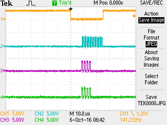
I would like to use the chip select CSHOLD in the SPIDAT1 transmit register. The CSHOLD works correctly except that there is a glitch on the CS line at the end of the first transfer. This glitch causes the SPI slave to not respond with data. See image below. The traces from top to bottom are, CS[0], clk, somi and simo.
#define CS_HIGH (0x01)
#define CS_LOW (0xFE)
SPIDat1Config(SOC_SPI_1_REGS, (SPI_CSHOLD | SPI_DATA_FORMAT0), CS_LOW);
SPIDefaultCSSet(SOC_SPI_1_REGS, CS_HIGH);
// order is c2edelay, t2edelay, t2cdelay, c2tdelay
SPIDelayConfigure(SOC_SPI_1_REGS, 0, 0, 100, 100);
CS_HIGH and CS_LOW can also be set to 0x01 and 0x00, but the behaviour is the same.
An external pulldown resistor on the CS[0] line does not make a change.
Various settings of the delay values does not make a change.
All the various Ti literature shows that the CSHOLD setting in the SPIDAT1 register is correct, for example;
Configuring SPI_CS Polarity
There is no single bit in the SPI registers which allows you specify the polarity of the SPI_CS pin(s). However, there are two register fields that allow you to specify the state of the SPI_CS pins when a data transfer is active and when there is no data transfer. The SPIDEF.CSDEF bits define the state of the SPI CS pins when there is no data transfer ongoing: 0 means set the pin low and 1 means set the pin high. Similarly, the SPIDAT1.CSNR bits define the state of the SPI CS pins when there is a transfer ongoing: 0 means set the pin low and 1 means set the pin high. Each bit in CSNR and CSDEF corresponds to a CS pin supported on the device. For example, CSNR[0] corresponds to SPI_CS0, CSNR[1] to SPI_CS1, etc. In the case your device only supports one CS pin, only bit 0 of these bit fields applies. If you want the SPI.CS0 pin to be active low, you want to have CSDEF[0] = 1 and CSNR[0] = 0.
from http://processors.wiki.ti.com/index.php/Using_SPI_Chip_Select_Pin_on_C674x/OMAP-L1x
QUESTION
Note the glitch on the CS[0] line. Why is the C6748 SPI_1 interface doing this?
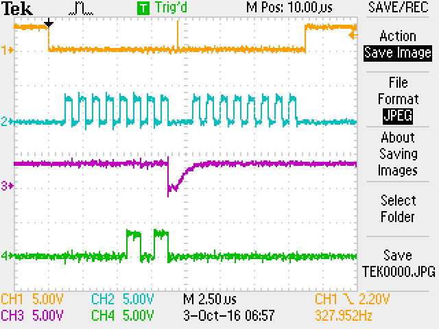
if the CS[0] line is instead configured as a GPIO line and the CS line is controlled externally, the CS[0] line behaves correctly. See the image below.
Note there is no glitch on the CS[0] line and the SPI slave responds correctly.
John