


Other Parts Discussed in Thread: SYSCONFIG
I'm trying to get spi working on a 5728, but when I try a transaction, the chip select drops low (active) for a short period of time and then goes high with no clock pulses at all.
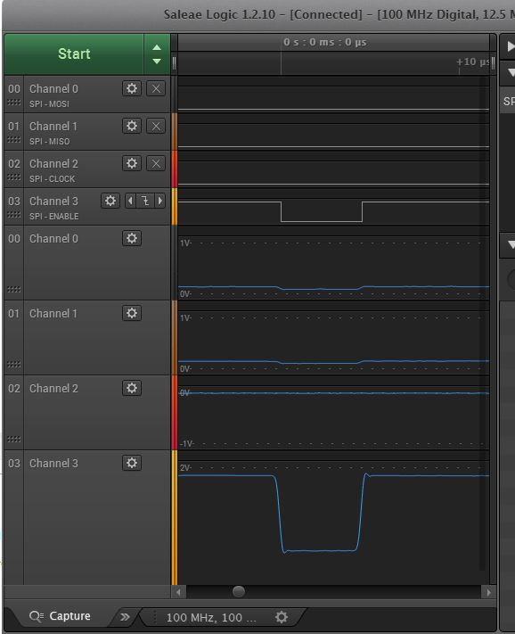
If I use spi->SYST to bit bang the bits out, individually setting bits and pausing with wait statements, it works fine.

My initialization code looks like this:
spi->SYSCONF = 0x30a; // clocks maintained; ignore idle mode request; turn off wakeup mode; reset spi
while (spi->SYSSTAUS & 0x1 != 1);
// clk div pwr of 2; no fifo; cs 3.5 cycle buffer; xmit (mosi) on d0 and not d1; xfer 8 bits; 1.5MHz clk; cpha=1 dat chg on rise clked on fall
spi->CSREG[1].CHxCONF = 0x060603d5;
spi->SYSCONF = 0x308; // clocks maintained; ignore idle mode request; turn off wakeup mode; don't reset spi this time
spi->HL_SYSCONFIG = 0x4; // no idle mode; sensitive to emulation suspend; don't reset
spi->MODULCTRL = 0x1; // single channel master
The code to transmit looks like this:
spi->CSREG[1].CHxCONF |= 0x00100000; // CSHOLD;
for (i = 0; i < in_length; i++)
{
// clear cs hold if we were told to set it and this is the last byte.
if ((SPI_HOLD_CLR == in_cs_hold) && (i == (in_length - 1)))
spi->CSREG[1].CHxCONF &= ~0x00100000; // CSHOLD;
spi->CSREG[1].TXx = *src_buffer;
// increment src pointer, if the caller is not using the same
// memory for src and dest.
src_buffer++;
// start the channel
spi->CSREG[1].CHxCTRL = 1;
while (!(spi->CSREG[1].CHxSTAT & 2));
// stop the channel
spi->CSREG[1].CHxCTRL = 0;
// copy the received data.
*dest_buffer = (uint8_t) (spi->CSREG[1].RXx);
dest_buffer++;
}
When I examine the contents of CM_L4PER_CLKSTCTRL I see 0x01f7ff02 which I believe indicates the 48 MHz spi functional clock is up and running.
If you're wondering why I'm directly accessing registers instead of using the drivers as in C:\ti\pdk_am57xx_1_0_3, it's because those examples are absolutely worthless. For example, what exactly does Board_init(boardCfg) do and how do I modify it for my custom board? When using SPI_init(), the comments say the SPI_config structure must exist and be persistent before this function can be called. The configuration structure is a large structure filled out with #defines like MCSPI_DATA_LINE_COMM_MODE_7 which expands to
((MCSPI_CH0CONF_IS_LINE1 << MCSPI_CH0CONF_IS_SHIFT) | (MCSPI_CH0CONF_DPE1_DISABLED << MCSPI_CH0CONF_DPE1_SHIFT) | \
(MCSPI_CH0CONF_DPE0_DISABLED << MCSPI_CH0CONF_DPE0_SHIFT))
with absolutely no comments whatsoever to explain how to modify this for my custom hardware. These aren't examples for someone to write their own code, they're test code for an EVM board with little to no thought about making it easy for someone to modify for their own board. Besides, when I tried to go down this path, I got compile errors that my field engineer couldn't tell me how to fix.


