This thread has been locked.

If you have a related question, please click the "Ask a related question" button in the top right corner. The newly created question will be automatically linked to this question.

AM335x wrong value read from ADC

Other Parts Discussed in Thread: AM3352

Dear Champs,

My customer found wrong value read in ADC0 of AM3352 when they insert 1kohm resistor on R356 in below.

When they remove this resistor, they can measured it as 0 ~ 1.67V, but, when they inserted 1k ohm on R356, they found 2.2V ~ 3.3V wave although they expected 1V. Could you please check below schematic for ADC_in0?

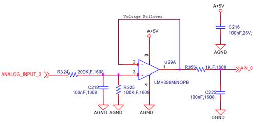
When they made OP-amp output as 1V in below, 

But, they found below resonance between 2.2V ~ 3.3V

Thanks and Best Regards,

SI.

  • AM335x ADC inputs cannot accept voltages higher than VDDA_ADC, which is 1.8V. Why is the voltage follower powered from 5V?
  • Dear Sung-IL,

    In addition to Biser's answer and important Caution, take in mind following specifics about  the applied voltage follower circuit.

    The problem with these passive filters is that frequency selectivity is achieved by dissipated unwanted frequencies and it is impossible for any frequency components in the input signal to be amplified by this type of filter.

    A capacitor and a resistor that hang on the output of an amplifier change the amplifier's open-loop-gain curve. The combination of the load capacitor, CL - the load resistor, RL - and the amplifier's open-loop resistance, RO (out) , introduces a pole to the open-loop-gain curve, and CL and RL then introduce a zero to the open-loop-gain curve, see the figure below. Creating this pole and zero does not disrupt the amplifier's stability as long as they cancel each other out before the open-loop-gain curve crosses the closed-loop-gain curve. If the open-loop-gain and closed-loop-gain curves cross with a 40-dB/decade closure rate, the amplifier circuit will be marginally unstable or, worse yet, will oscillate.

    You can find the pole and zero locations in this circuit in the following equations:

    I would recommend your customer to use following simple low pass filter for reducing ADC aliasing errors:

    Best regards,

    Yanko

  • Hi Yanko and Biser,

    Thanks for your fruitful answers.

    But, customer wants to get more details as below.

    1) Why the voltage follower's power will impact to AM3352? the output voltage of voltage followers connected to AM3352 ADC is managed under 1.8V.

    2) Even when they removed voltage followers from AM3352 ADC, they found similar resonance at around 3.3V when they set it as continuous mode. Is this normal?

    3) They got good result when they used one-shot mode, but they failed only in continuous mode. why this difference will be occurred? why this voltage follower is measured well only in one-shot mode?

    Thanks and Best Regards,

    SI.

  • The question here is where does this 3.3V level come from at the AIN input? They need to investigate this. There seems to be something wrong in the schematics around the ADC.
  • Biser,

    Thanks again for your response.
    Do you think it is possible to have an issue in their SW implementation of continuous mode because there was no issue in their one-shot mode? And there is no issue in their HW?


    Thanks and Best Regards,
    SI.
  • I cannot comment without seeing the complete schematic. As for software I do not know what they are using. Is it our SDK?
  • Biser,

    Are you Ok to share complete schematic and review it just for this issue? If you are Ok on this, I'll request it to customer.

    Their SW was linux-3.2-psp04.06.00.07.sdk.tar.gz and I think continuous mode is not supported in this version, right? So, I requested to implement continuous mode again refering below url which I found e2e, but they still failed. They also requested to check SW, but I don't know if we should check SW or HW. So, I need your help on this, and let me know your opinion.


    processors.wiki.ti.com/.../Linux_Core_ADC_User's_Guide

    beagleboard-gsoc13.blogspot.in/.../sampling-analogue-signals-using-adc-on.html

    beagleboard-gsoc13.blogspot.in/.../continuous-sampling-mode-for-adc-driver.html


    Thanks and Best Regards,
    SI.
  • Yes, you can send the schematic to my TI e-mail. As for the software, this version is obsolete and should not be used for new designs. It's no longer maintained or supported by the software team.