This thread has been locked.

If you have a related question, please click the "Ask a related question" button in the top right corner. The newly created question will be automatically linked to this question.

AM437x does not wake up from DeepSleep0 by TPS65218 button

Other Parts Discussed in Thread: TPS65218

Hi,

After I enter "echo mem > /sys/power/state" in kernel, the kernel can goto low power mode correctlly.

But I can't wake up it when I push the PB button for TPS65218.(I can only wake up the kernel through UART interrupt).

Does there any registers need to be configured for the PB button for wake up?

Thanks.

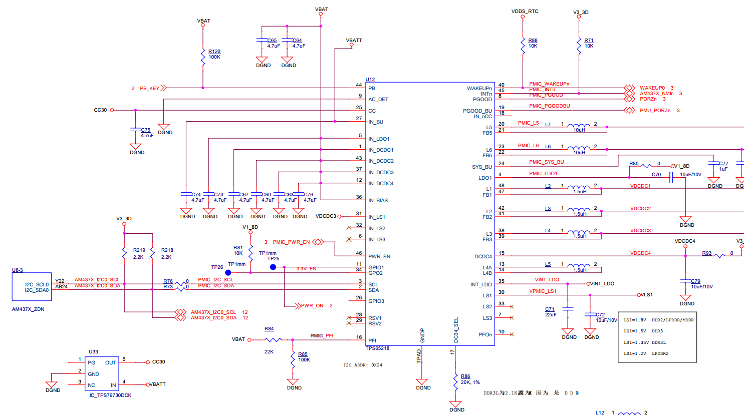
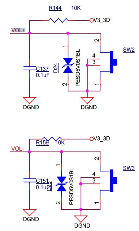
The following is my board schematic:

  • Hi,

    See section 6.4.5 on the AM437x TRM Rev. E. The PMIC power button is not a valid wakeup source from DeepSleep0. It can only be used for wake up from RTC-only mode
  • Thanks for you quickly reply!
    Well, this is a bad news for me.
    I want to use PB button and some other irqs to wake up the kernel.
    1. I have noticed that when I push the PB button, the PMIC will generate a PMIC_INT which is connected to AM437X_NMI, can this intterupt be used as a wakeup source?
    2. For other irqs(a gpio interrupt for example), can I set the irq as a wakeup source? How should I do?

    The scenario on my side is:
    The board enter DeepSleep0(or DeepSleep1?) when it found there is nothing to do, I want to wake it up when I push the PB button.
    There is another module on my board, when the module found data arrives it will generate a gpio interrupt, I wish this interrupt can wake up the kernel either, how should I do?
    Thank you very much!!!
  • The wakeup sources are listed in section 6.4.5 on the AM437x TRM Rev. E. You should connect to a GPIO0 pin to wake up the device.
  • I see...
    So only GPIO0 can be the wakeup source when the chip enter DeepSleep0, other GPIO can' be. Is it right?
    How about DeepSleep1(standby)?
    Table 6-13 in the TRM says standby can be "Wakeup from any GPIO", it means not only GPIO0 but all GPIOs can be a wakeup source, am I right?
    Thanks!
  • Yes, this is correct.
  • Got it!
    Thanks. I will do some test later.
    Thanks again!
  • Hi Biser Gatchev-XID,

    I have done some tests for gpio wake up, unfortunately it can't work on my board.

    My kernel is 3.14.

    My dts:

    ......

                   vol-down-key {

    gpios = <&gpio1 21 GPIO_ACTIVE_LOW>;

    linux,code = <114>;

    label = "volume down";

    debounce-interval = <1>;

    gpio-key,wakeup;

    };

    vol-up-key {

    gpios = <&gpio1 22 GPIO_ACTIVE_LOW>;

    linux,code = <115>;

    label = "volume up";

    debounce-interval = <1>;

    gpio-key,wakeup;

    };

    ......

    My test:

    root@am437x-evm:~# echo standby > /sys/power/state      

    [ 3440.098461] PM: Syncing filesystems ... done.

    [ 3440.122111] Freezing user space processes ... (elapsed 0.001 seconds) done.

    [ 3440.130849] Freezing remaining freezable tasks ... (elapsed 0.001 seconds) done.

    [ 3440.140089] Suspending console(s) (use no_console_suspend to debug)

    And then I push either the vol-down-key or the vol-up-key, they all can't wakeup the kernel, still only UART can wake up...

    [ 3440.153792] PM: suspend of devices complete after 6.067 msecs

    [ 3440.154566] PM: late suspend of devices complete after 0.751 msecs

    [ 3440.156089] PM: noirq suspend of devices complete after 1.498 msecs

    [ 3440.156320] PM: Successfully put all powerdomains to target state

    [ 3440.156320] PM: Wakeup source UART

    [ 3440.157915] PM: noirq resume of devices complete after 1.527 msecs

    [ 3441.967731] [sched_delayed] sched: RT throttling activated

    [ 3441.968725] PM: early resume of devices complete after 0.789 msecs

    The schematic:

    I have no idea why I can't wake up.

    Does this is a correct way?

    Thanks!

  • This is getting out of my area (hardware), so I have asked the PM experts to look at this. They will respond here.
  • That's will be wonderful!
    Thanks for your kindly help!!!
  • user4552302 said:
    My kernel is 3.14.

    So you use AM437x PSDK? If yes, which version? See if the below wiki page will be in help:

    http://processors.wiki.ti.com/index.php/Linux_Core_Power_Management_User's_Guide_%28v3.14%29

    Regards,
    Pavel

  • Hi Pavel Botev,
    Yes, I am using GPIO1 to do wake up.
    I know only GPIO0 can be used as wakeup source for DeepSleep0 mode.
    But I am using the standby mode, not DeepSleep0. And the TRM said any GPIOs can be a wakeup source for Standby mode.
    Thanks for you quickly reply!
  • Do you use AM437x PSDK? If yes, which version?

    See also if the below pointers will be in help:

     http://processors.wiki.ti.com/index.php/AM335x_Power_Management_Standby_User's_Guide

    http://processors.wiki.ti.com/index.php/AM335x_Linux_Power_Management_User_Guide

    Regards,

    Pavel

  • Hi,
    I am using ti-processor-sdk-linux-am437x-evm-01.00.00.00...
    Is it too old?
  • Hi user4552302,

    No, this SDK is not too old.

    Beside configuring the kernel device tree, you need also to make some GPIO sysfs settings, refer to the below links for more info:

    processors.wiki.ti.com/.../AM335x_Power_Management_Standby_User's_Guide
    processors.wiki.ti.com/.../Linux_PSP_GPIO_Driver_Guide
    git.ti.com/.../sysfs.txt

    e2e.ti.com/.../401936
    e2e.ti.com/.../278106

    Regards,
    Pavel
  • Hi,

    It seems that I need to do some setting for /sys/kernel/debug/omap_mux/board/standby_gpio_pad_conf.

    But I don't know why there is no standby_gpio_pad_conf file on my board.

    I just have a blank folder /sys/kernel/debug/omap_mux/board/.

    What were  missed ?

    Thanks.

  • user4552302 said:

    It seems that I need to do some setting for /sys/kernel/debug/omap_mux/board/standby_gpio_pad_conf.

    But I don't know why there is no standby_gpio_pad_conf file on my board.

    I just have a blank folder /sys/kernel/debug/omap_mux/board/.

    What were  missed ?

    I made some search and it seems that this standby_gpio_pad_conf feature is deprecated for linux kernel 3.12, 3.14 (and newer), it is valid for linux kernel 3.2 (TI SDK6). See the below pointers:

    ti-sdk-am335x-evm-06.00.00.00/board-support/linux-3.2.0-psp04.06.00.11/arch/arm/mach-omap2/mux33xx.c

    For PSDK1 (linux kernel 3.14), it should work when the pin is configured only for GPIO. See the below file for how to set up your dts file:

    linux-3.14.26/Documentation/devicetree/bindings/gpio/gpio_keys.txt

    You might also see the below dts files for example:

    linux-3.14.26/arch/arm/boot/dts/am335x-evmsk.dts

    linux-3.14.26/arch/arm/boot/dts/am335x-evm.dts

    linux-3.14.26/arch/arm/boot/dts/omap3-ldp.dts

    linux-3.14.26/arch/arm/boot/dts/omap3-beagle.dts

    If your pin is configured for other function (not GPIO), you should configure the GPIO mode as a "sleep" mode and the other main function as "default" (run-time). See the below wiki for more info:

    http://processors.wiki.ti.com/index.php/Linux_Core_Power_Management_User's_Guide_%28v3.14%29#IO_Pad_Configuration

    See also the below e2e threads:

    Regards,
    Pavel

  • Hi,

    I have checked my dts, and it seems no problem...

    I have checked the following logs:

    root@am437x-evm:~# cat /sys/kernel/debug/wakeup_sources

    name            active_count    event_count     wakeup_count    expire_count    active_since    total_time      max_time        last_change     prevent_suspend_time

    gpio-keys.7     2               2               0               0               0               0               0               64715           0

    I pushed the button to try to wakeup the system, it failed, then I use UART to wakeup.

    From the above logs, the GPIO seems have some effects on the system, since the count was changed.

    I attached my dts, could you please do me a favor to have a check with the file?

    I am using the VOL+/VOL- button to wake.

    Thank you!

    /*
     * Copyright (C) 2013 Texas Instruments Incorporated - http://www.ti.com/
     *
     * This program is free software; you can redistribute it and/or modify
     * it under the terms of the GNU General Public License version 2 as
     * published by the Free Software Foundation.
     */
    
    /* ROZH RH812 */
    
    /dts-v1/;
    
    #include "am4372.dtsi"
    #include <dt-bindings/pinctrl/am43xx.h>
    #include <dt-bindings/pwm/pwm.h>
    #include <dt-bindings/interrupt-controller/irq.h>
    
    / {
    	model = "ROZH RH812";
    	compatible = "rozh,rh812","ti,am4372","ti,am43";
    
    	aliases {
    		display0 = &lcd0;
    		serial3 = &uart3;
    	};
    
    	evm_v3_3d: fixedregulator-v3_3d {
    		compatible = "regulator-fixed";
    		regulator-name = "evm_v3_3d";
    		regulator-min-microvolt = <3300000>;
    		regulator-max-microvolt = <3300000>;
    		enable-active-high;
    	};
    
    	vtt_fixed: fixedregulator-vtt {
    		compatible = "regulator-fixed";
    		regulator-name = "vtt_fixed";
    		regulator-min-microvolt = <1500000>;
    		regulator-max-microvolt = <1500000>;
    		regulator-always-on;
    		regulator-boot-on;
    		enable-active-high;
    		gpio = <&gpio5 7 GPIO_ACTIVE_HIGH>;
    	};
    
    	lcd_bl: backlight {
    		compatible = "pwm-backlight";
    		pwms = <&ecap0 0 50000 PWM_POLARITY_INVERTED>;
    		brightness-levels = <0 50 100 150 200 250 255>;
    		default-brightness-level = <3>;
    	};
    
    	lcd0: display {
    		compatible = "osddisplays,osd057T0559-34ts", "panel-dpi";
    		label = "lcd";
    
    		panel-timing {
    			clock-frequency = <54000000>;
    			hactive = <1024>;
    			vactive = <600>;
    			hfront-porch = <360>;
    			hback-porch = <20>;
    			hsync-len = <20>;
    			vback-porch = <4>;
    			vfront-porch = <21>;
    			vsync-len = <6>;
    			hsync-active = <0>;
    			vsync-active = <0>;
    			de-active = <1>;
    			pixelclk-active = <1>;
    		};
    
    		port {
    			lcd_in: endpoint {
    				remote-endpoint = <&dpi_out>;
    			};
    		};
    	};
    
    	sound0: sound@0 {
    		compatible = "simple-audio-card";
    		simple-audio-card,name = "ROZH-812";
    		simple-audio-card,widgets =
    			"Microphone", "Microphone Jack",
    			"Headphone", "Headphone Jack",
    			"Line", "Line In";
    		simple-audio-card,routing =
    			"MIC3L", "Microphone Jack",
    			"MIC3R", "Microphone Jack",
    			"Microphone Jack", "Mic Bias",
    			"Headphone Jack",	"HPLOUT",
    			"Headphone Jack",	"HPROUT",
    			"LINE1L",		"Line In",
    			"LINE1R",		"Line In";
    		simple-audio-card,format = "dsp_b";
    		simple-audio-card,bitclock-master = <&link0_codec>;
    		simple-audio-card,frame-master = <&link0_codec>;
    		simple-audio-card,bitclock-inversion;
    
    		simple-audio-card,cpu {
    			sound-dai = <&mcasp0>;
    			system-clock-frequency = <12000000>;
    		};
    
    		link0_codec: simple-audio-card,codec {
    			sound-dai = <&tlv320aic3106>;
    			system-clock-frequency = <12000000>;
    		};
    	};
    
    	gpio-keys {
    		compatible = "gpio-keys";
    
    		power-key {
    			gpios = <&gpio1 20 GPIO_ACTIVE_HIGH>;
    			linux,code = <116>;
    			label = "keypwr";
    			debounce-interval = <1>;
    			gpio-key,wakeup;
    		};
    
    		vol-down-key {
    			gpios = <&gpio1 21 GPIO_ACTIVE_LOW>;
    			linux,code = <114>;
    			label = "volume down";
    			debounce-interval = <1>;
    			gpio-key,wakeup;
    		};
    
    		vol-up-key {
    			gpios = <&gpio1 22 GPIO_ACTIVE_LOW>;
    			linux,code = <115>;
    			label = "volume up";
    			debounce-interval = <1>;
    			gpio-key,wakeup;
    		};
    
    		key1 {
    			gpios = <&gpio1 23 GPIO_ACTIVE_HIGH>;
    			linux,code = <171>;
    			label = "key1";
    			debounce-interval = <1>;
    			gpio-key,wakeup;
    		};
    
    		key0 {
    			gpios = <&gpio1 24 GPIO_ACTIVE_HIGH>;
    			linux,code = <212>;
    			label = "key0";
    			debounce-interval = <1>;
    		};
    	};
    };
    
    &am43xx_pinmux {
    	pinctrl-names = "default", "sleep";
    	pinctrl-0 = <&wlan_pins_default &ddr3_vtt_toggle_default &gpio_keys_pins_default &power_pins>;
    	pinctrl-1 = <&wlan_pins_sleep>;
    
    	ddr3_vtt_toggle_default: ddr_vtt_toggle_default {
    		pinctrl-single,pins = <
    			0x25C (DS0_PULL_UP_DOWN_EN | PIN_OUTPUT_PULLUP | DS0_FORCE_OFF_MODE | MUX_MODE7) /* (N25) spi4_cs0.gpio5_7 */
    		>;
    	};
    
    	i2c0_pins: i2c0_pins {
    		pinctrl-single,pins = <
    			0x188 (PIN_INPUT_PULLUP | SLEWCTRL_FAST | MUX_MODE0)  /* i2c0_sda.i2c0_sda */
    			0x18c (PIN_INPUT_PULLUP | SLEWCTRL_FAST | MUX_MODE0)  /* i2c0_scl.i2c0_scl */
    		>;
    	};
    
    	i2c1_pins_default: i2c1_pins_default {
    		pinctrl-single,pins = <
    			0x240 (PIN_INPUT_PULLUP | SLEWCTRL_FAST | MUX_MODE1)  /* (G20) gpio5_10.I2C1_SCL */
    			0x248 (PIN_INPUT_PULLUP | SLEWCTRL_FAST | MUX_MODE1)  /* (E25) gpio5_12.I2C1_SDA */
    		>;
    	};
    
    	i2c1_pins_sleep: i2c1_pins_sleep {
    		pinctrl-single,pins = <
    			0x240 (PIN_INPUT_PULLUP | MUX_MODE7)
    			0x248 (PIN_INPUT_PULLUP | MUX_MODE7)
    		>;
    	};
    #if 1
    	i2c2_pins_default: i2c2_pins_default {
    		pinctrl-single,pins = <
    			0x17c (PIN_INPUT_PULLUP | SLEWCTRL_FAST | MUX_MODE3)  /* (L22) uart1_rtsn.I2C2_SCL */
    			0x178 (PIN_INPUT_PULLUP | SLEWCTRL_FAST | MUX_MODE3)  /* (K22) uart1_ctsn.I2C2_SDA */
    		>;
    	};
    #endif
    #if 0
    	i2c2_pins_sleep: i2c2_pins_sleep {
    		pinctrl-single,pins = <
    			0x17c (PIN_INPUT_PULLUP | MUX_MODE7)
    			0x178 (PIN_INPUT_PULLUP | MUX_MODE7)
    		>;
    	};
    #endif
    	mmc1_pins: pinmux_mmc1_pins {
    		pinctrl-single,pins = <
    			0x100 (PIN_INPUT_PULLUP | MUX_MODE0) /* (D1) mmc0_clk.mmc0_clk */
    			0x104 (PIN_INPUT_PULLUP | MUX_MODE0) /* (D2) mmc0_cmd.mmc0_cmd */
    			0x0f0 (PIN_INPUT_PULLUP | MUX_MODE0) /* (C1) mmc0_dat0.mmc0_dat0 */
    			0x0f4 (PIN_INPUT_PULLUP | MUX_MODE0) /* (C2) mmc0_dat1.mmc0_dat1 */
    			0x0f8 (PIN_INPUT_PULLUP | MUX_MODE0) /* (B2) mmc0_dat2.mmc0_dat2 */
    			0x0fc (PIN_INPUT_PULLUP | MUX_MODE0) /* (B1) mmc0_dat3.mmc0_dat3 */
    #if 0
    			0x160 (PIN_INPUT | MUX_MODE7) /* (R25) spi0_cs1.mmc0_pow */
    #endif
    		>;
    	};
    
    	mmc1_sleep_pins: pinmux_mmc1_sleep_pins {
    		pinctrl-single,pins = <
    			0x100 (PIN_INPUT_PULLDOWN | MUX_MODE7)
    			0x104 (PIN_INPUT | PULL_DISABLE | MUX_MODE7)
    			0x0f0 (PIN_INPUT | PULL_DISABLE | MUX_MODE7)
    			0x0f4 (PIN_INPUT | PULL_DISABLE | MUX_MODE7)
    			0x0f8 (PIN_INPUT | PULL_DISABLE | MUX_MODE7)
    			0x0fc (PIN_INPUT | PULL_DISABLE | MUX_MODE7)
    #if 0
    			0x160 (PIN_INPUT | PULL_DISABLE | MUX_MODE7)
    #endif
    		>;
    	};
    
    	emmc_pins_default: emmc_pins_default {
    		pinctrl-single,pins = <
    			0x00 (PIN_INPUT_PULLUP | MUX_MODE1) /* gpmc_ad0.mmc1_dat0 */
    			0x04 (PIN_INPUT_PULLUP | MUX_MODE1) /* gpmc_ad1.mmc1_dat1 */
    			0x08 (PIN_INPUT_PULLUP | MUX_MODE1) /* gpmc_ad2.mmc1_dat2 */
    			0x0c (PIN_INPUT_PULLUP | MUX_MODE1) /* gpmc_ad3.mmc1_dat3 */
    			0x10 (PIN_INPUT_PULLUP | MUX_MODE1) /* gpmc_ad4.mmc1_dat4 */
    			0x14 (PIN_INPUT_PULLUP | MUX_MODE1) /* gpmc_ad5.mmc1_dat5 */
    			0x18 (PIN_INPUT_PULLUP | MUX_MODE1) /* gpmc_ad6.mmc1_dat6 */
    			0x1c (PIN_INPUT_PULLUP | MUX_MODE1) /* gpmc_ad7.mmc1_dat7 */
    			0x80 (PIN_INPUT_PULLUP | MUX_MODE2) /* gpmc_csn1.mmc1_clk */
    			0x84 (PIN_INPUT_PULLUP | MUX_MODE2) /* gpmc_csn2.mmc1_cmd */
    		>;
    	};
    
    	emmc_pins_sleep: emmc_pins_sleep {
    		pinctrl-single,pins = <
    			0x00 (PIN_INPUT_PULLDOWN | MUX_MODE7) /* gpmc_ad0.gpio1_0 */
    			0x04 (PIN_INPUT_PULLDOWN | MUX_MODE7) /* gpmc_ad1.gpio1_1 */
    			0x08 (PIN_INPUT_PULLDOWN | MUX_MODE7) /* gpmc_ad2.gpio1_2 */
    			0x0c (PIN_INPUT_PULLDOWN | MUX_MODE7) /* gpmc_ad3.gpio1_3 */
    			0x10 (PIN_INPUT_PULLDOWN | MUX_MODE7) /* gpmc_ad4.gpio1_4 */
    			0x14 (PIN_INPUT_PULLDOWN | MUX_MODE7) /* gpmc_ad5.gpio1_5 */
    			0x18 (PIN_INPUT_PULLDOWN | MUX_MODE7) /* gpmc_ad6.gpio1_6 */
    			0x1c (PIN_INPUT_PULLDOWN | MUX_MODE7) /* gpmc_ad7.gpio1_7 */
    			0x80 (PIN_INPUT_PULLDOWN | MUX_MODE7) /* gpmc_csn1.gpio1_30 */
    			0x84 (PIN_INPUT_PULLDOWN | MUX_MODE7) /* gpmc_csn2.gpio1_31 */
    		>;
    	};
    
    	ecap0_pins_default: backlight_pins_default {
    		pinctrl-single,pins = <
    			0x164 MUX_MODE0       /* eCAP0_in_PWM0_out.eCAP0_in_PWM0_out MODE0 */
    		>;
    	};
    
    	ecap0_pins_sleep: backlight_pins_sleep {
    		pinctrl-single,pins = <
    			0x164 (PIN_INPUT_PULLDOWN | MUX_MODE7)
    		>;
    	};
    
    	touch_int_pins: touch_int_pins {
    		pinctrl-single,pins = <
    			0x254 ( PIN_INPUT_PULLUP | MUX_MODE7 ) /* (R24) spi4_d0.gpio5_5 TS_INT */
    			0x250 ( PIN_OUTPUT | MUX_MODE7 ) /* (P25) spi4_sclk.gpio5[4] TS_RST */
    			0x1ac ( PIN_OUTPUT | MUX_MODE7 ) /* (L24) mcasp0_ahclkx.gpio3[21] TS_PWR */
    		>;
    	};
    
    	davinci_mdio_default: davinci_mdio_default {
    		pinctrl-single,pins = <
    			/* MDIO */
    			0x148 (PIN_INPUT_PULLUP | SLEWCTRL_FAST | MUX_MODE0)	/* mdio_data.mdio_data */
    			0x14c (PIN_OUTPUT_PULLUP | MUX_MODE0)			/* mdio_clk.mdio_clk */
    		>;
    	};
    
    	davinci_mdio_sleep: davinci_mdio_sleep {
    		pinctrl-single,pins = <
    			/* MDIO reset value */
    			0x148 (PIN_INPUT | PULL_DISABLE | MUX_MODE7)
    			0x14c (PIN_INPUT | PULL_DISABLE | MUX_MODE7)
    		>;
    	};
    
    	dss_pinctrl_default: dss_pinctrl_default {
    		pinctrl-single,pins = <
    			0xe0 ( PIN_OUTPUT_PULLUP | MUX_MODE0 ) /* (B23) dss_vsync.dss_vsync */
    			0xe4 ( PIN_OUTPUT_PULLUP | MUX_MODE0 ) /* (A23) dss_hsync.dss_hsync */
    			0xe8 ( PIN_OUTPUT_PULLUP | MUX_MODE0 ) /* (A22) dss_pclk.dss_pclk */
    			0xec ( PIN_OUTPUT_PULLUP | MUX_MODE0 ) /* (A24) dss_ac_bias_en.dss_ac_bias_en */
    			0xa0 ( PIN_OUTPUT_PULLUP | MUX_MODE0 ) /* (B22) dss_data0.dss_data0 */
    			0xa4 ( PIN_OUTPUT_PULLUP | MUX_MODE0 ) /* (A21) dss_data1.dss_data1 */
    			0xa8 ( PIN_OUTPUT_PULLUP | MUX_MODE0 ) /* (B21) dss_data2.dss_data2 */
    			0xac ( PIN_OUTPUT_PULLUP | MUX_MODE0 ) /* (C21) dss_data3.dss_data3 */
    			0xb0 ( PIN_OUTPUT_PULLUP | MUX_MODE0 ) /* (A20) dss_data4.dss_data4 */
    			0xb4 ( PIN_OUTPUT_PULLUP | MUX_MODE0 ) /* (B20) dss_data5.dss_data5 */
    			0xb8 ( PIN_OUTPUT_PULLUP | MUX_MODE0 ) /* (C20) dss_data6.dss_data6 */
    			0xbc ( PIN_OUTPUT_PULLUP | MUX_MODE0 ) /* (E19) dss_data7.dss_data7 */
    			0xc0 ( PIN_OUTPUT_PULLUP | MUX_MODE0 ) /* (A19) dss_data8.dss_data8 */
    			0xc4 ( PIN_OUTPUT_PULLUP | MUX_MODE0 ) /* (B19) dss_data9.dss_data9 */
    			0xc8 ( PIN_OUTPUT_PULLUP | MUX_MODE0 ) /* (A18) dss_data10.dss_data10 */
    			0xcc ( PIN_OUTPUT_PULLUP | MUX_MODE0 ) /* (B18) dss_data11.dss_data11 */
    			0xd0 ( PIN_OUTPUT_PULLUP | MUX_MODE0 ) /* (C19) dss_data12.dss_data12 */
    			0xd4 ( PIN_OUTPUT_PULLUP | MUX_MODE0 ) /* (D19) dss_data13.dss_data13 */
    			0xd8 ( PIN_OUTPUT_PULLUP | MUX_MODE0 ) /* (C17) dss_data14.dss_data14 */
    			0xdc ( PIN_OUTPUT_PULLUP | MUX_MODE0 ) /* (D17) dss_data15.dss_data15 */
    			0x3c ( PIN_OUTPUT_PULLUP | MUX_MODE1 ) /* (A11) gpmc_ad15.dss_data16 */
    			0x38 ( PIN_OUTPUT_PULLUP | MUX_MODE1 ) /* (B11) gpmc_ad14.dss_data17 */
    			0x34 ( PIN_OUTPUT_PULLUP | MUX_MODE1 ) /* (C11) gpmc_ad13.dss_data18 */
    			0x30 ( PIN_OUTPUT_PULLUP | MUX_MODE1 ) /* (E11) gpmc_ad12.dss_data19 */
    			0x2c ( PIN_OUTPUT_PULLUP | MUX_MODE1 ) /* (D11) gpmc_ad11.dss_data20 */
    			0x28 ( PIN_OUTPUT_PULLUP | MUX_MODE1 ) /* (F11) gpmc_ad10.dss_data21 */
    			0x24 ( PIN_OUTPUT_PULLUP | MUX_MODE1 ) /* (A10) gpmc_ad9.dss_data22 */
    			0x20 ( PIN_OUTPUT_PULLUP | MUX_MODE1 ) /* (B10) gpmc_ad8.dss_data23 */
    
    			0x64 ( PIN_OUTPUT_PULLUP | MUX_MODE7 ) /* (B4) gpmc_a9.gpio1[25] RST_LCD */
    			0x20c ( PIN_OUTPUT_PULLUP | MUX_MODE7 ) /* (AB18) cam0_data1.cam0_data1 gpio5_20 PDB*/
    		>;
    	};
    #if 0
    	dss_pinctrl_sleep: dss_pinctrl_sleep {
    		pinctrl-single,pins = <
    			0xe0 (DS0_PULL_UP_DOWN_EN | PIN_INPUT_PULLDOWN | MUX_MODE7)
    			0xe4 (DS0_PULL_UP_DOWN_EN | PIN_INPUT_PULLDOWN | MUX_MODE7)
    			0xe8 (DS0_PULL_UP_DOWN_EN | PIN_INPUT_PULLDOWN | MUX_MODE7)
    			0xec (DS0_PULL_UP_DOWN_EN | PIN_INPUT_PULLDOWN | MUX_MODE7)
    			0xa0 (DS0_PULL_UP_DOWN_EN | PIN_INPUT_PULLDOWN | MUX_MODE7)
    			0xa4 (DS0_PULL_UP_DOWN_EN | PIN_INPUT_PULLDOWN | MUX_MODE7)
    			0xa8 (DS0_PULL_UP_DOWN_EN | PIN_INPUT_PULLDOWN | MUX_MODE7)
    			0xac (DS0_PULL_UP_DOWN_EN | PIN_INPUT_PULLDOWN | MUX_MODE7)
    			0xb0 (DS0_PULL_UP_DOWN_EN | INPUT_EN | PULL_DISABLE | MUX_MODE7)
    			0xb4 (DS0_PULL_UP_DOWN_EN | INPUT_EN | PULL_DISABLE | MUX_MODE7)
    			0xb8 (DS0_PULL_UP_DOWN_EN | INPUT_EN | PULL_DISABLE | MUX_MODE7)
    			0xbc (DS0_PULL_UP_DOWN_EN | INPUT_EN | PULL_DISABLE | MUX_MODE7)
    			0xc0 (DS0_PULL_UP_DOWN_EN | INPUT_EN | PULL_DISABLE | MUX_MODE7)
    			0xc4 (DS0_PULL_UP_DOWN_EN | INPUT_EN | PULL_DISABLE | MUX_MODE7)
    			0xc8 (DS0_PULL_UP_DOWN_EN | INPUT_EN | PULL_DISABLE | MUX_MODE7)
    			0xcc (DS0_PULL_UP_DOWN_EN | PIN_INPUT_PULLDOWN | MUX_MODE7)
    			0xd0 (DS0_PULL_UP_DOWN_EN | PIN_INPUT_PULLDOWN | MUX_MODE7)
    			0xd4 (DS0_PULL_UP_DOWN_EN | INPUT_EN | PULL_DISABLE | MUX_MODE7)
    			0xd8 (DS0_PULL_UP_DOWN_EN | PIN_INPUT_PULLDOWN | MUX_MODE7)
    			0xdc (DS0_PULL_UP_DOWN_EN | PIN_INPUT_PULLDOWN | MUX_MODE7)
    			0x3c (DS0_PULL_UP_DOWN_EN | INPUT_EN | PULL_DISABLE | MUX_MODE7)
    			0x38 (DS0_PULL_UP_DOWN_EN | INPUT_EN | PULL_DISABLE | MUX_MODE7)
    			0x34 (DS0_PULL_UP_DOWN_EN | INPUT_EN | PULL_DISABLE | MUX_MODE7)
    			0x30 (DS0_PULL_UP_DOWN_EN | PIN_INPUT_PULLDOWN | MUX_MODE7)
    			0x2c (DS0_PULL_UP_DOWN_EN | PIN_INPUT_PULLDOWN | MUX_MODE7)
    			0x28 (DS0_PULL_UP_DOWN_EN | PIN_INPUT_PULLDOWN | MUX_MODE7)
    			0x24 (DS0_PULL_UP_DOWN_EN | PIN_INPUT_PULLDOWN | MUX_MODE7)
    			0x20 (DS0_PULL_UP_DOWN_EN | PIN_INPUT_PULLDOWN | MUX_MODE7)
    
    			0x64 ( PIN_OUTPUT_PULLUP | MUX_MODE7 ) /* (B4) gpmc_a9.gpio1[25] RST_LCD */
    			0x68 ( PIN_OUTPUT_PULLUP | MUX_MODE7 ) /* (G8) gpmc_a10.gpio1[26] LCD_PWR*/
    		>;
    	};
    #endif
    	mmc3_pins_default: pinmux_mmc3_pins_default {
    		pinctrl-single,pins = <
    			0x8c ( PIN_INPUT_PULLUP | MUX_MODE3 ) /* (A12) gpmc_clk.mmc2_clk */
    			0x88 ( PIN_INPUT_PULLUP | MUX_MODE3 ) /* (B12) gpmc_csn3.mmc2_cmd */
    			0x44 ( PIN_INPUT_PULLUP | MUX_MODE3 ) /* (C5) gpmc_a1.mmc2_dat0 */
    			0x48 ( PIN_INPUT_PULLUP | MUX_MODE3 ) /* (C6) gpmc_a2.mmc2_dat1 */
    			0x4c ( PIN_INPUT_PULLUP | MUX_MODE3 ) /* (A4) gpmc_a3.mmc2_dat2 */
    			0x78 ( PIN_INPUT_PULLUP | MUX_MODE3 ) /* (A3) gpmc_be1n.mmc2_dat3 */
    		>;
    	};
    #if 1
    	mmc3_pins_sleep: pinmux_mmc3_pins_sleep {
    		pinctrl-single,pins = <
    			0x8c (PIN_OUTPUT_PULLDOWN | MUX_MODE7)	/* gpmc_clk.mmc2_clk */
    			0x88 (PIN_OUTPUT_PULLDOWN | MUX_MODE7)	/* gpmc_csn3.mmc2_cmd */
    			0x44 (PIN_OUTPUT_PULLDOWN | MUX_MODE7)	/* gpmc_a1.mmc2_dat0 */
    			0x48 (PIN_OUTPUT_PULLDOWN | MUX_MODE7)	/* gpmc_a2.mmc2_dat1 */
    			0x4c (PIN_OUTPUT_PULLDOWN | MUX_MODE7)	/* gpmc_a3.mmc2_dat2 */
    			0x78 (PIN_OUTPUT_PULLDOWN | MUX_MODE7)	/* gpmc_be1n.mmc2_dat3 */
    		>;
    	};
    #endif
    	wlan_pins_default: pinmux_wlan_pins_default {
    		pinctrl-single,pins = <
    			0x23c ( PIN_OUTPUT_PULLUP | MUX_MODE7 ) /* (F24) gpio5_9.gpio5[9] WLAN_EN */
    			0x160 ( PIN_INPUT | MUX_MODE7 ) /* (R25) spi0_cs1.gpio0[6] WIFI_IRQ */
    			0x6c ( PIN_INPUT | MUX_MODE7 ) /* (D8) gpmc_a11.gpio1[27] WL_WAKE */
    			0x21c ( PIN_OUTPUT_PULLUP | MUX_MODE7 ) /* (AD19) cam0_data5.cam0_data5 WIFI_PWR */
    		>;
    	};
    
    	wlan_pins_sleep: pinmux_wlan_pins_sleep {
    		pinctrl-single,pins = <
    			0x23c ( PIN_OUTPUT_PULLDOWN | MUX_MODE7 ) /* (F24) gpio5_9.gpio5[9] WLAN_EN */
    			0x160 ( PIN_INPUT_PULLDOWN | MUX_MODE7 ) /* (R25) spi0_cs1.gpio0[6] WIFI_IRQ */
    			0x6c ( PIN_INPUT_PULLDOWN | MUX_MODE7 ) /* (D8) gpmc_a11.gpio1[27] WL_WAKE */
    			0x21c ( PIN_OUTPUT_PULLDOWN | MUX_MODE0 ) /* (AD19) cam0_data5.cam0_data5 WIFI_PWR */
    		>;
    	};
    
    	uart3_pins: uart3_pins {
    		pinctrl-single,pins = <
    			0x228 (PIN_INPUT | MUX_MODE0) 		/* uart3_rxd.uart3_rxd */
    			0x22c (PIN_OUTPUT_PULLDOWN | MUX_MODE0) /* uart3_txd.uart3_txd */
    			0x230 (PIN_INPUT_PULLUP | MUX_MODE0) 	/* uart3_ctsn.uart3_ctsn */
    			0x234 (PIN_OUTPUT_PULLDOWN | MUX_MODE0) /* uart3_rtsn.uart3_rtsn */
    		>;
    	};
    
    	mcasp1_pins: mcasp1_pins {
    		pinctrl-single,pins = <
    			0x190 ( PIN_INPUT_PULLDOWN | MUX_MODE0 ) /* (N24) mcasp0_aclkx.mcasp0_aclkx */
    			0x194 ( PIN_INPUT_PULLDOWN | MUX_MODE0 ) /* (N22) mcasp0_fsx.mcasp0_fsx */
    			0x1a0 ( PIN_OUTPUT_PULLDOWN | MUX_MODE2 ) /* (L23) mcasp0_aclkr.mcasp0_axr2 */
    			0x1a4 ( PIN_INPUT_PULLDOWN | MUX_MODE2 ) /* (K23) mcasp0_fsr.mcasp0_axr3 */
    		>;
    	};
    #if 0
    	mcasp1_sleep_pins: mcasp1_sleep_pins {
    		pinctrl-single,pins = <
    			0x108 (PIN_INPUT_PULLDOWN | MUX_MODE7)
    			0x10c (PIN_INPUT_PULLDOWN | MUX_MODE7)
    			0x110 (PIN_INPUT_PULLDOWN | MUX_MODE7)
    			0x144 (PIN_INPUT_PULLDOWN | MUX_MODE7)
    		>;
    	};
    #endif
    	vpfe1_pins_default: vpfe1_pins_default {
    		pinctrl-single,pins = <
    		#if 0
    			0x1c0 ( PIN_OUTPUT_PULLUP | MUX_MODE0 ) /* (AC20) cam0_pclk.cam0_pclk CAM_RST */
    			0x1b0 ( PIN_OUTPUT_PULLUP | MUX_MODE0 ) /* (AE17) cam0_hd.cam0_hd MT_CTRL */
    			0x1b4 ( PIN_OUTPUT_PULLUP | MUX_MODE0 ) /* (AD18) cam0_vd.cam0_vd CAM_PWDN */
    			0x208 ( PIN_OUTPUT_PULLUP | MUX_MODE0 ) /* (AE18) cam0_data0.cam0_data0 CAM_DOVDDEN */
    		#endif
    			0x1d4 ( PIN_INPUT_PULLUP | MUX_MODE0 ) /* (AD25) cam1_hd.cam1_hd */
    			0x1d8 ( PIN_INPUT_PULLUP | MUX_MODE0 ) /* (AC23) cam1_vd.cam1_vd */
    			0x1e0 ( PIN_INPUT_PULLUP | MUX_MODE0 ) /* (AC25) cam1_field.cam1_field */
    			0x1e4 ( PIN_INPUT_PULLUP | MUX_MODE0 ) /* (AB25) cam1_wen.cam1_wen */
    			0x1dc ( PIN_INPUT_PULLUP | MUX_MODE0 ) /* (AE21) cam1_pclk.cam1_pclk */
    			0x1e8 ( PIN_INPUT_PULLUP | MUX_MODE0 ) /* (AB20) cam1_data0.cam1_data0 */
    			0x1ec ( PIN_INPUT_PULLUP | MUX_MODE0 ) /* (AC21) cam1_data1.cam1_data1 */
    			0x1f0 ( PIN_INPUT_PULLUP | MUX_MODE0 ) /* (AD21) cam1_data2.cam1_data2 */
    			0x1f4 ( PIN_INPUT_PULLUP | MUX_MODE0 ) /* (AE22) cam1_data3.cam1_data3 */
    			0x1f8 ( PIN_INPUT_PULLUP | MUX_MODE0 ) /* (AD22) cam1_data4.cam1_data4 */
    			0x1fc ( PIN_INPUT_PULLUP | MUX_MODE0 ) /* (AE23) cam1_data5.cam1_data5 */
    			0x200 ( PIN_INPUT_PULLUP | MUX_MODE0 ) /* (AD23) cam1_data6.cam1_data6 */
    			0x204 ( PIN_INPUT_PULLUP | MUX_MODE0 ) /* (AE24) cam1_data7.cam1_data7 */
    			0x1d0 ( PIN_INPUT_PULLUP | MUX_MODE0 ) /* (AD24) cam1_data8.cam1_data8 */
    			0x1cc ( PIN_INPUT_PULLUP | MUX_MODE0 ) /* (AC24) cam1_data9.cam1_data9 */
    		>;
    	};
    #if 0
    	vpfe1_pins_sleep: vpfe1_pins_sleep {
    		pinctrl-single,pins = <
    			0x1c0 ( PIN_OUTPUT_PULLDOWN | MUX_MODE0 ) /* (AC20) cam0_pclk.cam0_pclk CAM_RST */
    			0x1b0 ( PIN_OUTPUT_PULLDOWN | MUX_MODE0 ) /* (AE17) cam0_hd.cam0_hd MT_CTRL */
    			0x1b4 ( PIN_OUTPUT_PULLDOWN | MUX_MODE0 ) /* (AD18) cam0_vd.cam0_vd CAM_PWDN */
    			0x208 ( PIN_OUTPUT_PULLDOWN | MUX_MODE0 ) /* (AE18) cam0_data0.cam0_data0 CAM_DOVDDEN */
    
    			0x1d4 ( DS0_PULL_UP_DOWN_EN | INPUT_EN | MUX_MODE7 ) /* (AD25) cam1_hd.cam1_hd */
    			0x1d8 ( DS0_PULL_UP_DOWN_EN | INPUT_EN | MUX_MODE7 ) /* (AC23) cam1_vd.cam1_vd */
    			0x1e0 ( DS0_PULL_UP_DOWN_EN | INPUT_EN | MUX_MODE7 ) /* (AC25) cam1_field.cam1_field */
    			0x1e4 ( DS0_PULL_UP_DOWN_EN | INPUT_EN | MUX_MODE7 ) /* (AB25) cam1_wen.cam1_wen */
    			0x1dc ( DS0_PULL_UP_DOWN_EN | INPUT_EN | MUX_MODE7 ) /* (AE21) cam1_pclk.cam1_pclk */
    			0x1e8 ( DS0_PULL_UP_DOWN_EN | INPUT_EN | MUX_MODE7 ) /* (AB20) cam1_data0.cam1_data0 */
    			0x1ec ( DS0_PULL_UP_DOWN_EN | INPUT_EN | MUX_MODE7 ) /* (AC21) cam1_data1.cam1_data1 */
    			0x1f0 ( DS0_PULL_UP_DOWN_EN | INPUT_EN | MUX_MODE7 ) /* (AD21) cam1_data2.cam1_data2 */
    			0x1f4 ( DS0_PULL_UP_DOWN_EN | INPUT_EN | MUX_MODE7 ) /* (AE22) cam1_data3.cam1_data3 */
    			0x1f8 ( DS0_PULL_UP_DOWN_EN | INPUT_EN | MUX_MODE7 ) /* (AD22) cam1_data4.cam1_data4 */
    			0x1fc ( DS0_PULL_UP_DOWN_EN | INPUT_EN | MUX_MODE7 ) /* (AE23) cam1_data5.cam1_data5 */
    			0x200 ( DS0_PULL_UP_DOWN_EN | INPUT_EN | MUX_MODE7 ) /* (AD23) cam1_data6.cam1_data6 */
    			0x204 ( DS0_PULL_UP_DOWN_EN | INPUT_EN | MUX_MODE7 ) /* (AE24) cam1_data7.cam1_data7 */
    			0x1d0 ( DS0_PULL_UP_DOWN_EN | INPUT_EN | MUX_MODE7 ) /* (AD24) cam1_data8.cam1_data8 */
    			0x1cc ( DS0_PULL_UP_DOWN_EN | INPUT_EN | MUX_MODE7 ) /* (AC24) cam1_data9.cam1_data9 */			
    		>;
    	};
    #endif
    	uart0_pins_default: uart0_pins_default {
    		pinctrl-single,pins = <
    			0x168 (DS0_PULL_UP_DOWN_EN | INPUT_EN | MUX_MODE0)
    			0x16C (DS0_PULL_UP_DOWN_EN | INPUT_EN | MUX_MODE0)
    			0x170 (PIN_INPUT_PULLUP | SLEWCTRL_FAST | DS0_PULL_UP_DOWN_EN | MUX_MODE0) /* uart0_rxd.uart0_rxd */
    			0x174 (PIN_INPUT | PULL_DISABLE | SLEWCTRL_FAST | DS0_PULL_UP_DOWN_EN | MUX_MODE0) /* uart0_txd.uart0_txd */
    		>;
    	};
    
    	uart0_pins_sleep: uart0_pins_sleep {
    		pinctrl-single,pins = <
    			0x168 (DS0_PULL_UP_DOWN_EN | INPUT_EN | MUX_MODE7)
    			0x16C (DS0_PULL_UP_DOWN_EN | INPUT_EN | MUX_MODE7)
    			0x170 (PIN_INPUT_PULLUP | SLEWCTRL_FAST | DS0_PULL_UP_DOWN_EN | MUX_MODE0) /* uart0_rxd.uart0_rxd */
    			0x174 (PIN_INPUT_PULLDOWN | SLEWCTRL_FAST | DS0_PULL_UP_DOWN_EN | MUX_MODE0) /* uart0_txd.uart0_txd */
    		>;
    	};
    
    	usb2_phy1_default: usb2_phy1_default {
    		pinctrl-single,pins = <
    			0x2c0 (DS0_PULL_UP_DOWN_EN | PIN_INPUT_PULLDOWN | MUX_MODE0)	/* (G21) drvvbus */
    		>;
    	};
    
    	usb2_phy1_sleep: usb2_phy1_sleep {
    		pinctrl-single,pins = <
    			0x2c0 (DS0_PULL_UP_DOWN_EN | PIN_INPUT_PULLDOWN | MUX_MODE7)	/* (G21) drvvbus */
    		>;
    	};
    
    	usb2_phy2_default: usb2_phy2_default {
    		pinctrl-single,pins = <
    			0x2c4 (DS0_PULL_UP_DOWN_EN | PIN_INPUT_PULLDOWN | MUX_MODE0)	/* (F25) drvvbus */
    		>;
    	};
    
    	usb2_phy2_sleep: usb2_phy2_sleep {
    		pinctrl-single,pins = <
    			0x2c4 (DS0_PULL_UP_DOWN_EN | PIN_INPUT_PULLDOWN | MUX_MODE7)	/* (F25) drvvbus */
    		>;
    	};
    #if 0
    	qspi1_default: qspi1_default {
    		pinctrl-single,pins = <
    			0x88 ( PIN_INPUT_PULLUP | MUX_MODE2) 	/* (B12) gpmc_csn3.qspi_clk shared with wifi_mmc_cmd */
    			0x7c ( PIN_INPUT_PULLUP | MUX_MODE3 ) /* (A8) gpmc_csn0.qspi_csn */
    			0x90 ( PIN_INPUT_PULLUP | MUX_MODE3 ) /* (A9) gpmc_advn_ale.qspi_d0 */
    			0x94 ( PIN_INPUT_PULLUP | MUX_MODE3 ) /* (E10) gpmc_oen_ren.qspi_d1 */
    			0x98 ( PIN_INPUT_PULLUP | MUX_MODE3 ) /* (D10) gpmc_wen.qspi_d2 */
    			0x9c ( PIN_INPUT_PULLUP | MUX_MODE3 ) /* (C10) gpmc_be0n_cle.qspi_d3 */
    		>;
    	};
    #endif
    	spi0_pins_default: spi0_pins_default {
    		pinctrl-single,pins = <
    			0x150 ( PIN_INPUT_PULLDOWN | MUX_MODE0 ) /* (P23) spi0_sclk.spi0_sclk ZIG_SCK */
    			0x154 ( PIN_OUTPUT_PULLDOWN | MUX_MODE0 ) /* (T22) spi0_d0.spi0_d0 ZIG_MOSI */
    			0x158 ( PIN_INPUT_PULLDOWN | MUX_MODE0 ) /* (T21) spi0_d1.spi0_d1 ZIG_MISO */
    			0x15c ( PIN_OUTPUT_PULLDOWN | MUX_MODE0 ) /* (T20) spi0_cs0.spi0_cs0 ZIG_SEL */
    		>;
    	};
    
    	zigbee_pins: zigbee_pins {
    		pinctrl-single,pins = <
    			0x40 ( PIN_INPUT_PULLDOWN | MUX_MODE7 ) /* (C3) gpmc_a0.gpio1[16] ZIG_IRQ */
    			0x244 ( PIN_OUTPUT_PULLDOWN | MUX_MODE7 ) /* (F23) gpio5_11.gpio5[11] V_ZIG33_EN */
    			0x24c ( PIN_OUTPUT_PULLUP | MUX_MODE7 ) /* (E24) gpio5_13.gpio5[13] ZIG_RST */
    		>;
    	};
    
    	gpio_keys_pins_default: gpio_keys_pins_default {
    		pinctrl-single,pins = <
    			0x50 ( PIN_OUTPUT_PULLUP | MUX_MODE7 ) /* (D7) gpmc_a4.gpio1[20] KEYPWR */
    			0x54 ( PIN_INPUT | MUX_MODE7 ) /* (E7) gpmc_a5.gpio1[21] VOL- */
    			0x58 ( PIN_INPUT | MUX_MODE7 ) /* (E8) gpmc_a6.gpio1[22] VOL+ */
    			0x5c ( PIN_INPUT | MUX_MODE7 ) /* (F6) gpmc_a7.gpio1[23] KEY1 */
    			0x60 ( PIN_INPUT | MUX_MODE7 ) /* (F7) gpmc_a8.gpio1[24] KEY0 */
    		>;
    	};
    
    	power_pins: power_pins {
    		pinctrl-single,pins = <
    			0x68 ( PIN_OUTPUT_PULLUP | MUX_MODE7 ) /* lcd_pwr */
    			0x270 ( PIN_OUTPUT_PULLUP | MUX_MODE3 ) /* clkout1 */
    			0x268 ( PIN_OUTPUT_PULLUP | MUX_MODE7 ) /* audio_pwr */
    			0x19c ( PIN_OUTPUT_PULLUP | MUX_MODE7 ) /* audio_i2cen */
    			0x1a8 ( PIN_OUTPUT_PULLUP | MUX_MODE7 ) /* aud_reset */
    			0x26c ( PIN_OUTPUT | MUX_MODE7 ) /* audiopa_sd */
    			0x198 ( PIN_OUTPUT_PULLUP | MUX_MODE7 ) /* 5v_en */
    			0x220 ( PIN_OUTPUT_PULLUP | MUX_MODE7 ) /* bat_3g */
    			0x210 ( PIN_OUTPUT_PULLUP | MUX_MODE7 ) /* pwr_3g */
    			0x214 ( PIN_OUTPUT_PULLUP | MUX_MODE7 ) /* rst_3g */
    			0x1c0 ( PIN_OUTPUT | MUX_MODE7 ) /* cam_rst */
    			0x1b4 ( PIN_OUTPUT | MUX_MODE7 ) /* cam_pwdn */
    			0x208 ( PIN_OUTPUT | MUX_MODE7 ) /* cam_dovdden */
    			0x260 ( PIN_OUTPUT | MUX_MODE7 ) /* cam_2v8en */
    			0x1b8 ( PIN_OUTPUT | MUX_MODE7 ) /* AC18, gpio4_2 Charger_EN */
    			0x1bc ( PIN_OUTPUT | MUX_MODE7 ) /* AD17, gpio4_3 OnlyChg */
    			0x1c8 ( PIN_OUTPUT | MUX_MODE7 ) /* AA19, gpio4_6 OTG */
    			0x1b0 ( PIN_OUTPUT | MUX_MODE7 ) /* mt_ctrl */
    			0x264 ( PIN_OUTPUT | MUX_MODE7 ) /* (P22) spi2_d0.spi2_d0 FLASH_LED */
    			0x218 ( PIN_OUTPUT | MUX_MODE7 ) /* (AE19) cam0_data4.cam0_data4 FLASH_LED_EN */
    		>;
    	};
    };
    
    &i2c0 {
    	status = "okay";
    	pinctrl-names = "default";
    	pinctrl-0 = <&i2c0_pins>;
    	clock-frequency = <100000>;
    
        eeprom: eeprom@50 {
    		compatible = "at,24c256";
    		reg = <0x50>;
    	};
    
    	tps65218: tps65218@24 {
    		reg = <0x24>;
    		compatible = "ti,tps65218";
    		interrupts = <GIC_SPI 7 IRQ_TYPE_NONE>; /* NMIn */
    		interrupt-parent = <&gic>;
    		interrupt-controller;
    		#interrupt-cells = <2>;
    
    		dcdc1: regulator-dcdc1 {
    			compatible = "ti,tps65218-dcdc1";
    			regulator-name = "vdd_core";
    			regulator-min-microvolt = <912000>;
    			regulator-max-microvolt = <1144000>;
    			regulator-boot-on;
    			regulator-always-on;
    		};
    
    		dcdc2: regulator-dcdc2 {
    			compatible = "ti,tps65218-dcdc2";
    			regulator-name = "vdd_mpu";
    			regulator-min-microvolt = <912000>;
    			regulator-max-microvolt = <1378000>;
    			regulator-boot-on;
    			regulator-always-on;
    		};
    
    		dcdc3: regulator-dcdc3 {
    			compatible = "ti,tps65218-dcdc3";
    			regulator-name = "vdcdc3";
    			regulator-suspend-enable;
    			regulator-min-microvolt = <1500000>;
    			regulator-max-microvolt = <1500000>;
    			regulator-boot-on;
    			regulator-always-on;
    		};
    
    		dcdc5: regulator-dcdc5 {
    			compatible = "ti,tps65218-dcdc5";
    			regulator-name = "v1_0bat";
    			regulator-min-microvolt = <1000000>;
    			regulator-max-microvolt = <1000000>;
    		};
    
    		dcdc6: regulator-dcdc6 {
    			compatible = "ti,tps65218-dcdc6";
    			regulator-name = "v1_8bat";
    			regulator-min-microvolt = <1800000>;
    			regulator-max-microvolt = <1800000>;
    		};
    
    		ldo1: regulator-ldo1 {
    			compatible = "ti,tps65218-ldo1";
    			regulator-min-microvolt = <1800000>;
    			regulator-max-microvolt = <1800000>;
    			regulator-boot-on;
    			regulator-always-on;
    		};
    	};
    };
    
    &i2c1 {
    	status = "okay";
    	pinctrl-names = "default";//, "sleep";
    	pinctrl-0 = <&i2c1_pins_default>;
    	//pinctrl-1 = <&i2c1_pins_sleep>;
    
    	tlv320aic3106: tlv320aic3106@1b {
    		#sound-dai-cells = <0>;
    		compatible = "ti,tlv320aic3106";
    		reg = <0x1b>;
    		status = "okay";
    
    		/* Regulators */
    		AVDD-supply = <&evm_v3_3d>;
    		IOVDD-supply = <&evm_v3_3d>;
    		DRVDD-supply = <&evm_v3_3d>;
    		DVDD-supply = <&ldo1>;
    		ai3x-micbias-vg = <1>;
    	};
    
    	ov5640@3c {
    		compatible = "ti,ov5640";
    		reg = <0x3c>;
    		port {
    			ov5640_0: endpoint {
    				remote-endpoint = <&vpfe1_ep>;
    				mclk-frequency = <24000000>;
    			};
    		};
    	};
    
    	bq25890@6A{
    		compatible = "ti,bq2589x-1";
    		reg = <0x6A>;
    		interrupts = <61 0x2>;
    		ti,bq2589x,vbus-volt-high-level = <8700>;/* tune adapter to output 9v */
    		ti,bq2589x,vbus-volt-low-level = <4400>;/* tune adapter to output 5v */
    		ti,bq2589x,vbat-min-volt-to-tuneup = <3000>;
    		ti,bq2589x,charge-voltage = <4208>;
    		ti,bq2589x,charge-current = <2000>;
    		ti,bq2589x,term-current = <256>;
    
    		ti,bq2589x,enable-auto-dpdm;
    		ti,bq2589x,enable-termination;
    		ti,bq2589x,enable-ico;
    		ti,bq2589x,use-absolute-vindpm;
    	};
    
    	bq25892@6B{
    		compatible = "ti,bq2589x-2";
    		reg = <0x6B>;
    	};
    };
    #if 1
    &i2c2 {
    	status = "okay";
    	#if 0
    	pinctrl-names = "default", "sleep";
    	#else
    	pinctrl-names = "default";
    	#endif
    	pinctrl-0 = <&i2c2_pins_default>;
    #if 0
    	pinctrl-1 = <&i2c2_pins_sleep>;
    #endif
    
    	gt970: touchscreen@5d {
    		/* gt970 is compatible with gt967 */
    		compatible = "goodix,gt967";
    		reg = <0x5d>;
    		interrupt-parent = <&gpio5>;
    		interrupts = <5 0>;
    		pinctrl-names = "default";
    		pinctrl-0 = <&touch_int_pins>;
    		/* don't configure the gpio here */
    		#if 0
    		irq-gpios = <&gpio5 5 0 GPIO_ACTIVE_HIGH>;
    		reset-gpios = <&gpio5 5 4 GPIO_ACTIVE_HIGH>;
    		touchscreen-swapped-x-y;
    		#endif
    	};
    };
    #endif
    &epwmss0 {
    	status = "okay";
    };
    
    &tscadc {
            status = "okay";
    
            adc {
                    ti,adc-channels = <0 1 2 3 4 5 6 7>;
            };
    };
    
    &ecap0 {
    	status = "okay";
    	pinctrl-names = "default", "sleep";
    	pinctrl-0 = <&ecap0_pins_default>;
    	pinctrl-1 = <&ecap0_pins_sleep>;
    };
    
    &gpio0 {
    	status = "okay";
    };
    
    &gpio1 {
    	status = "okay";
    };
    
    &gpio2 {
    	status = "okay";
    };
    
    &gpio3 {
    	status = "okay";
    };
    
    &gpio4 {
    	status = "okay";
    };
    
    &gpio5 {
    	status = "okay";
    	ti,no-reset-on-init;
    };
    
    &mmc1 {
    	status = "okay";
    	vmmc-supply = <&evm_v3_3d>;
    	bus-width = <4>;
    	pinctrl-names = "default", "sleep";
    	pinctrl-0 = <&mmc1_pins>;
    	pinctrl-1 = <&mmc1_sleep_pins>;
    	cd-gpios = <&gpio0 6 GPIO_ACTIVE_HIGH>;
    };
    
    /* eMMC sits on mmc2 */
    &mmc2 {
    	status = "okay";
    	vmmc-supply = <&evm_v3_3d>;
    	bus-width = <8>;
    	pinctrl-names = "default", "sleep";
    	pinctrl-0 = <&emmc_pins_default>;
    	pinctrl-1 = <&emmc_pins_sleep>;
    	ti,non-removable;
    };
    
    #if 0
    /* wlan sits on mmc3 */
    &mmc3 {
    	status = "okay";
    	vmmc-supply = <&evm_v3_3d>;
    	bus-width = <4>;
    	pinctrl-names = "default";//, "sleep";
    	pinctrl-0 = <&mmc3_pins_default>;
    	//pinctrl-1 = <&mmc3_pins_sleep>;
    	ti,non-removable;
    };
    #endif
    
    &mmc3 {
    	status = "okay";
    	/* these are on the crossbar and are outlined in the
    	   xbar-event-map element */
    	dmas = <&edma 30
    		&edma 31>;
    	dma-names = "tx", "rx";
    	vmmc-supply = <&evm_v3_3d>;
    	bus-width = <4>;
    	pinctrl-names = "default", "sleep";
    	pinctrl-0 = <&mmc3_pins_default>;
    	pinctrl-1 = <&mmc3_pins_sleep>;
    	cap-power-off-card;
    	keep-power-in-suspend;
    #if 0
    	ti,non-removable;
    #endif
    
    #if 0
    	#address-cells = <1>;
    	#size-cells = <0>;
    	wlcore: wlcore@0 {
    		compatible = "ti,wlcore";
    		reg = <2>;
    		interrupt-parent = <&gpio1>;
    		interrupts = <23 IRQ_TYPE_NONE>;
    	};
    #endif	
    };
    
    &edma {
    	ti,edma-xbar-event-map = /bits/ 16 <1 30
    				  	    2 31>;
    };
    
    &uart3 {
    	status = "okay";
    	pinctrl-names = "default";
    	pinctrl-0 = <&uart3_pins>;
    };
    
    &dwc3_1 {
    	pinctrl-names = "default", "sleep";
    	pinctrl-0 = <&usb2_phy1_default>;
    	pinctrl-1 = <&usb2_phy1_sleep>;
    };
    
    &usb2_phy1 {
    	status = "okay";
    };
    
    &usb1 {
    	dr_mode = "otg";
    	status = "okay";
    };
    
    &dwc3_2 {
    	pinctrl-names = "default", "sleep";
    	pinctrl-0 = <&usb2_phy2_default>;
    	pinctrl-1 = <&usb2_phy2_sleep>;
    };
    
    &usb2_phy2 {
    	status = "okay";
    };
    
    &usb2 {
    	dr_mode = "host";
    	status = "okay";
    };
    
    &davinci_mdio {
    	pinctrl-names = "default", "sleep";
    	pinctrl-0 = <&davinci_mdio_default>;
    	pinctrl-1 = <&davinci_mdio_sleep>;
    	status = "okay";
    };
    
    &elm {
    	status = "okay";
    };
    
    &uart0 {
    	status = "okay";
    	pinctrl-names = "default", "sleep";
    	pinctrl-0 = <&uart0_pins_default>;
    	pinctrl-1 = <&uart0_pins_sleep>;
    };
    
    &dss {
    	status = "ok";
    
    	pinctrl-names = "default";
    	pinctrl-0 = <&dss_pinctrl_default>;
    
    	port {
    		dpi_out: endpoint@0 {
    			remote-endpoint = <&lcd_in>;
    			data-lines = <24>;
    		};
    	};
    };
    
    &mcasp0 {
    	#sound-dai-cells = <0>;
    #if 0
    	pinctrl-names = "default", "sleep";
    	pinctrl-0 = <&mcasp1_pins>;
    	pinctrl-1 = <&mcasp1_sleep_pins>;
    #else
    	pinctrl-names = "default";
    	pinctrl-0 = <&mcasp1_pins>;
    #endif
    	status = "okay";
    
    	op-mode = <0>; /* MCASP_IIS_MODE */
    	tdm-slots = <2>;
    	/* 4 serializers */
    	serial-dir = <  /* 0: INACTIVE, 1: TX, 2: RX */
    		0 0 1 2
    	>;
    	tx-num-evt = <32>;
    	rx-num-evt = <32>;
    };
    
    &cpu {
    	cpu0-supply = <&dcdc2>;
    };
    
    &rtc {
            status = "okay";
    };
    
    &wkup_m3 {
    	ti,set-io-isolation;
    	ti,scale-data-fw = "am43x-evm-scale-data.bin";
    };
    
    &vpfe1 {
    	status = "okay";
    #if 0
    	pinctrl-names = "default", "sleep";
    	pinctrl-0 = <&vpfe1_pins_default>;
    	pinctrl-1 = <&vpfe1_pins_sleep>;
    #else
    	pinctrl-names = "default";
    	pinctrl-0 = <&vpfe1_pins_default>;
    #endif
    #if 1
    	/* Camera port */
    	port {
    		vpfe1_ep: endpoint {
    			remote-endpoint = <&ov5640_0>;
    			if_type = <2>;
    			bus_width = <8>;
    			hdpol = <0>;
    			vdpol = <0>;
    		};
    	};
    #endif
    };
    #if 0
    /* Enable qspi, 16MB S25FL128S norflash */
    &qspi {
    	/*	Since the qspi will be used only at boot stage,
    			rh812 designer think the qspi clock can be shared.
    			The qspi clk is shared with wifi_mmc_cmd pin,
    			so after the kernel run, we can't operate qspi flash if we need
    			to keep the wifi worked.
    			I set the qspi to be disabled here, because we need to use wifi
    			after kerenl run.
    			If we need to operated the qspi flash in kernel also, we need to
    			change the hardware design.
    	*/
    	status = "disabled";
    	pinctrl-names = "default";
    	pinctrl-0 = <&qspi1_default>;
    
    	qspi-gpio = <&gpio1 16 GPIO_ACTIVE_LOW>;
    	spi-max-frequency = <24000000>;
    	m25p80@0 {
    		compatible = "s25fl128s";
    		spi-max-frequency = <24000000>;
    		reg = <0>;
    		spi-cpol;
    		spi-cpha;
    		spi-tx-bus-width = <1>;
    		spi-rx-bus-width = <4>;
    		#address-cells = <1>;
    		#size-cells = <1>;
    
    		/* MTD partition table.
    		 * The ROM checks the first 512KiB
    		 * for a valid file to boot(XIP).
    		 */
    		partition@0 {
    			label = "QSPI.U_BOOT";
    			reg = <0x00000000 0x000080000>;
    		};
    		partition@1 {
    			label = "QSPI.U_BOOT.backup";
    			reg = <0x00080000 0x00080000>;
    		};
    		partition@2 {
    			label = "QSPI.U_BOOT_ENV";
    			reg = <0x00100000 0x00020000>;
    		};
    		partition@3 {
    			label = "QSPI.U-BOOT-ENV.backup";
    			reg = <0x00120000 0x00020000>;
    		};
    		partition@4 {
    			label = "QSPI.U-BOOT-DEVICETREE";
    			reg = <0x00140000 0x00010000>;
    		};
    		partition@5 {
    			label = "QSPI.KERNEL";
    			reg = <0x00150000 0x0500000>;
    		};
    		partition@6 {
    			label = "QSPI.FILESYSTEM";
    			reg = <0x00650000 0x9B0000>;
    		};
    	};
    };
    #endif
    &spi0 {
    	ti,pindir-d0-out-d1-in = <1>;
    	status = "okay";
    	pinctrl-names = "default";
    	pinctrl-0 = <&spi0_pins_default>;
    #if 0
    	zigbee: zigbee {
    		pinctrl-names = "default";
    		pinctrl-0 = <&zigbee_pins>;
    		interrupt-parent = <&gpio1>;
    		interrupts = <16 0>;
    	};
    #endif
    };
    

  • Hi user4552302,

    On the AM335x TI EVM, we have audio volum up/down push buttons (SW9 and SW10), which are described in the linux-3.14.26/arch/arm/boot/dts/am335x-evm.dts.

    gpio_keys: volume_keys@0 {
    compatible = "gpio-keys";
    #address-cells = <1>;
    #size-cells = <0>;
    autorepeat;

    switch@9 {
    label = "volume-up";
    linux,code = <115>;
    gpios = <&gpio0 2 GPIO_ACTIVE_LOW>;
    gpio-key,wakeup;
    };

    switch@10 {
    label = "volume-down";
    linux,code = <114>;
    gpios = <&gpio0 3 GPIO_ACTIVE_LOW>;
    gpio-key,wakeup;
    };
    };

    Make sure you are aligned with that DTS and with the AM335x TI EVM schematics also, regarding these push buttons.
    www.ti.com/.../tmdxevm3358 - ARM MPU AM335x EVM General Purpose Daughterboard Schematic (Rev 1.1B) (Rev. A)

    Can you dump the pinmux value of your GPIO pinmux registers just before start the standby procedure (you can get the values with devmem2)?

    Regards,
    Pavel
  • Hi,
    I have follow the am335x-evm.dts, but still can't wake up...
    I have noticed that the GPIO used in am335x-evm.dts were GPIO0, but I am using the GPIO1.
    Does there any different when wake up from standby mode?

    Here are my gpio pinmux dump:
    root@am437x-evm:~# devmem2 0x44e10854
    /dev/mem opened.
    Memory mapped at address 0xb6fb3000.
    Read at address  0x44E10854 (0xb6fb3854): 0x00040007
    root@am437x-evm:~# devmem2 0x44e10858
    /dev/mem opened.
    Memory mapped at address 0xb6f31000.
    Read at address  0x44E10858 (0xb6f31858): 0x00040007
    root@am437x-evm:~#

    Thanks!

  • User4552302,

    I see that wakeup is not enabled in the 0x44e10854/0x44e10858 registers.

    CTRL_CONF_GPMC_A5[29] WUEN = 0
    CTRL_CONF_GPMC_A6[29] WUEN = 0

    Wakeup— I/O PAD can be individually enabled for wakeup using PADCONFx.WUEN register bit. The wakeup controls and events (as well as enable and disable controls) travels through asynchronously through the chain during DeepSleep. The global wakeup chain is enabled/controlled by the PRCM. This is global control is achieved by qualifying each of the I/O PAD wakeup enables with global wakeup daisy chain control coming from PRCM.

    Can you try the below modification in your DTS:

    gpio_keys_pins_default: gpio_keys_pins_default {
    pinctrl-single,pins = <

    0x54 ( WAKEUP_ENABLE | PIN_INPUT | MUX_MODE7 ) /* (E7) gpmc_a5.gpio1[21] VOL- */
    0x58 ( WAKEUP_ENABLE | PIN_INPUT | MUX_MODE7 ) /* (E8) gpmc_a6.gpio1[22] VOL+ */

    >;


    See the below file for more info:
    linux-3.14.26/include/dt-bindings/pinctrl/am43xx.h


    Can you also provide me the value of PRCM_PRM_IO_PMCTRL register?

    Regards,
    Pavel
  • Hi,

    I have followed your advice, but the GPIO1 still can't wake up.

    Here is my registers dump:

    root@am437x-evm:~# echo no > /sys/module/printk/parameters/console_suspend
    root@am437x-evm:~# devmem2 0x44df4024
    /dev/mem opened.
    Memory mapped at address 0xb6fc5000.
    Read at address 0x44DF4024 (0xb6fc5024): 0x00010020
    root@am437x-evm:~# devmem2 0x44e10854
    /dev/mem opened.
    Memory mapped at address 0xb6f72000.
    Read at address 0x44E10854 (0xb6f72854): 0x20050007
    root@am437x-evm:~# devmem2 0x44e10858
    /dev/mem opened.
    Memory mapped at address 0xb6f2b000.
    Read at address 0x44E10858 (0xb6f2b858): 0x20050007
    root@am437x-evm:~#
    root@am437x-evm:~# echo standby > /sys/power/state
    [ 579.787502] PM: Syncing filesystems ... done.
    [ 579.804760] Freezing user space processes ... (elapsed 0.001 seconds) done.
    [ 579.813576] Freezing remaining freezable tasks ... (elapsed 0.001 seconds) done.
    [ 579.829880] PM: suspend of devices complete after 6.109 msecs
    [ 579.836790] PM: late suspend of devices complete after 0.752 msecs
    [ 579.844919] PM: noirq suspend of devices complete after 1.438 msecs

  • user4552302,

    I see you are using internal pull in the pinmux settings. As you are using external pull-up, you do not need internal. Can you try with removing the internal pull (up/down) feature?

    Can you also provide me the value of PRCM_CM_PER_GPIO1_CLKCTRL register (before suspend and after wake-up from uart)?

    Can you provide me GPIO1 register dump before suspend and after wake-up from uart (with button switched between suspend and wake-up)? See AM437x TRM, section 28.3.3 Interrupt and Wake-up Features, for what you should have in these registers.

    Also, when you switch the button, you should have transition from 1 to 0 on the GPIO1 pin. Can you verify this through the sysfs or kernel (gpio_get_value) or with scope? See also the below wiki pages:

    processors.wiki.ti.com/.../Linux_PSP_GPIO_Driver_Guide
    processors.wiki.ti.com/.../Processor_SDK_Linux_GPIO_Driver_Overview

    Regards,
    Pavel