This thread has been locked.

If you have a related question, please click the "Ask a related question" button in the top right corner. The newly created question will be automatically linked to this question.

AM335x RTOS issues

so i am working on our new board and i am new to the 3352 and ARM in general. i am tasked with getting it up and running.

So we have a custom board. i am using the Beagle Bone Black gel file as a base (because it was more recent than the 335xEVm gel file). i am using EVM software as an example on how to enable the clock domains and modules. we are doing TI RTOS for the operation of the software

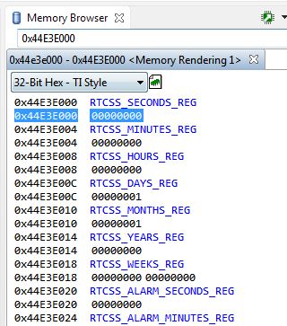
currently, i am unable to see the RTC registers or the LCDC registers. when i look at the registers in the "registers" window i get an error, when i look at them in the memory browser i get "???????" instead of values. when i try to enable the RTCSS module the code hangs waiting for:

while((PRCM_MODULE_IDLEST_FUNC << PRCM_IDLE_ST_SHIFT) != (*clkCtrlReg & PRCM_IDLE_ST_MASK));

the LCD module enables just fine and in the moment it gets enabled i can see the first 4 registers, but when i try to change any values it gives me an error and running a few instructions later it gives me the same error as the rtc registers like i can't see it at all

i should also note that when booting i cannot get to main unless i include a line to prevent the timer from checking the frequency of the input clock. i always get an error and it ends at the _exit routine

what i think is going on is at least one of my clocks is wrong i think it is the PER clock, however according tot he clock tree tool the settings i have in the gel file are dead on to get the right frequencies.

i am used to the C6748 DSP which doesn't do any of this clock gating. since this is my first experience with this i can safely say that the clocking on this part is kicking my butt

attached is my gel file:

Model840i_3352 GEL.zip

  • The RTOS team have been notified. They will respond here.
  • for accessing the RTCSS, are following the steps described in section 20.3.4 in the TRM:

    for reference example code for using RTC and LCDC, please refer to starterware examples include in the Processor SDK RTOS.


    You can find it in Processor SDK RTOS release under the directory path :

    pdk_am335x_1_x_x\package\ti\starterware\examples\rtc

    pdk_am335x_1_x_x\package\ti\starterware\examples\lcdc

    Hope this helps

    Regards,

    Rahul

  • that does not help but thanks anyway. i don't need help configuring it. i need to be able to access the registers and that is not happening
  • cobsonchael,

    I was able to access the RTC registers with just the GEL loaded on my AM335x GPEVM. I looked at your gel file and noticed the changes to the CLKIN values. 

    I have asked a colleague more familiar with the clock tree tool to comment on the settings.

    Is your boot image also doing some clock settings aside of the gel?

    Lali

  • all memory is blank. like i said i am completely new to this so i haven't even tackled booting yet. i'm working on getting emulation to work first.

  • still waiting for the colleague to weigh in

  • In order to access the registers of any module, you have to make sure its functional clock is enabled. What is the value of RTC_OCS_REG? Are you trying to use an external 32K crystal or the internally generated 32K from the PER PLL? If you are trying to use external, check the board to make sure the 32K crystal is operating properly (when the oscillator is enabled, you should be able to see a clock).

    Try switching SEL_32KCLK_SRC to 0 if you are unsure of your 32K clock source.

    Regards,
    James
  • i would check out that register value if i could access it. as my previous post shows all my RTC registers are ????? so i cannot check any RTC register values. i cannot turn on the external oscillator because i cannot access the register and if it is the functional clock i cannot access the registers because the clock can't be turned on. i will try switching the clock source but it seems like i should be able to access the RTC registers if for nothing else than to enable the external crystal

    also i was under the impression i was going to get my clock settings in my GEL file looked at to verify they are correct (according to the clock tree tool they are)

  • sooo...what am i missing?  am i missing a piece of advice that i misinterpreted and thought i cannot do?

    i know i need to turn on the RTC functional clock to access the registers, i feel like i did that and i still cannot access the registers. i am following the EVM example of how to turn on different modules and that doesn't seem to do anything. it seemed like another poster was able to access the registers just by loading the GEL file. so if that means my GEL file is wrong. and if it is wrong i don't know what is wrong with it because it seems like the clock tree tool agrees and i should be getting the right frequencies at the settings i have.  

  • I was able to gain access to the RTC registers using your GEL as is on our EVM.  When you connect thru JTAG, it should automatically run the intialization for the chip (should see output in the console window).  At this point, RTC regs at 0x44e30000 should show mostly zeros.  You can add the following script in the GEL and run it, and then you will be able to read/write the RTC registers.

    menuitem "RTC"
    hotmenu SetupRTC()
    {
    WR_MEM_32(0x44e00804,0x2);
    WR_MEM_32(0x44e00800,0x2);
    WR_MEM_32(0x44e3e06c,0x83E70B13);
    WR_MEM_32(0x44e3e070,0x95a4f1e0);
    WR_MEM_32(0x44e3e044,0xc0);

    WR_MEM_32(0x44e3e098,0x10000);
    WR_MEM_32(0x44e3e054,0x0);
    WR_MEM_32(0x44e3e07c,0x02);
    WR_MEM_32(0x44e3e078,0x3);

    WR_MEM_32(0x44e3e048,0x18);
    WR_MEM_32(0x44e3e054,0x48);
    }

    Regards,

    James

  • alright so if i change nothing i should be able to at least view the RTC registers, even without running your extra script? because when i run our GEL file, as is, i get all ????????'s for all values. 

    does this imply we have something wrong with the way our JTAG is setup/routed/layed out?

  • What if you open up a memory window somewhere other than the RTC?  Try 0x40300000.  That's internal memory.  If you can read/modify/write that area, then i don't think there is anything wrong with your JTAG.

    As for RTC, if you are still getting ????, you might have an issue with the functional clock.  What the value at 0x44e00804 (RTC_CLKSTCTRL)?  That will indicate if the RTC clock is active. 

    You may also have power issues.  The RTC is powered on its own domain with VDDS_RTC.  Refer to the wiki below.  Ensure that you have the proper connections according to the table in the wiki:  

    Regards,

    James

  • most other memory locations are fine. there are a lot of modules that i can activate and use, the only other exception that i have found is the LCDC module which also has a lot of ?????? in the memory window even after turning on the module

    i will check that register again and make sure it is active (but the fact that you were able to see the registers using just the GEL file implies i should too)

    i will double check the power connections

  • checking the register shows everything is active

  • it looks like our RTC circuit is getting the correct voltage but our RTC_PWRONRSTn is connected to a 3.3V supply and is at 2.60V and it looks like it's supposed to be 1.8V max. likely that is our problem. in addition, that 3.3V supply which is likely being brought down by connecting it to the 1.8V tolerant pin and is at 2.6V is also the supply to other things on the board so that might explain why i am having difficulties in other areas. looks like a board rev for us

    thanks for your help. hard to believe we overlooked this.
  • so how does this affect the LCD controller?

    when i enable the controller running this code:

    pass = PRCMModuleEnable(CHIPDB_MOD_ID_LCDC, 0U, 0U);

    which runs this code:

    enableModule(CM_PER_LCDC_CLKCTRL,

                    CM_PER_LCDC_CLKSTCTRL,

                    CM_PER_LCDC_CLKSTCTRL_CLKACTIVITY_LCDC_L3_OCP_GCLK);

    which runs this code:

    void enableModule(volatile U32 *clkCtrlReg, volatile U32 *clkStCtrlReg, U32 clkActMask)

    {

       /* Enable the module */

       *clkCtrlReg = PRCM_MODULEMODE_ENABLE;

       /* Check for module enable status */

       while(PRCM_MODULEMODE_ENABLE != (*clkCtrlReg & PRCM_MODULEMODE_MASK));

       /* Check clock activity - ungated */

       while(clkActMask != (*clkStCtrlReg & clkActMask));

       /* Check idle status value - should be in functional state */

       while((PRCM_MODULE_IDLEST_FUNC << PRCM_IDLE_ST_SHIFT) != (*clkCtrlReg & PRCM_IDLE_ST_MASK));

    }

    i get this result in my register view


    and my register CM_PER_LCDC_CLKCTRL is all active

    however in CM_PER_LCDC_CLKSTCTRL register the field CLKACTIVITY_LCDC_L4_OCP_GCLK is inactive but in the register CM_PER_L4LS_CLKSTCTRL it shows CLKACTIVITY_LCDC_GCLK as active

    i'm a bit lost as to how to turn this on

    after 1 refresh of the register view, without running ANY code, same halt session i get this for the LCD registers:

    so nothing really "stuck" as far as the clock is concerned

  • I did a quick check and I get the same errors when trying to see the LCD controller registers.  I seem to recall that these may not be accessible through the CCS memory window.  If i remember correctly, you wouldn't want to read/write these through the JTAG window because it triggers too many accesses which ends up confusing the controller anyway.  I'll have to look at it after the holidays

    Regards,

    James

  • i can understand that when it comes to a status register or an interrupt register, but why wouldn't i be able to see the timing registers? the frame buffer base/ceiling? why would it show me the first 4 registers for 1 instance and then when i hit refresh i can no longer read them anymore?

  • cobsonchael,

    Referring to the the AM335x RTOS package Starteware example located at C:\ti\pdk_am335x_1_0_5\packages\ti\starterware\examples\lcdc\lcdc_app.c

    software-dl.ti.com/.../index_FDS.html

    Are you doing all the steps as shown in the example in LCDCAppInit()?

    int32_t LCDCAppInit(lcdcAppObj_t *pLcdc)
    {
        int32_t status = E_FAIL;
    
        /* Select the input clock source for deriving the pixel clock. */
        SOCCtrlLcdcPixelClkSelect();
    
        /* Clock configuration */
        status = PRCMModuleEnable(CHIPDB_MOD_ID_LCDC, 0U, FALSE);
        if (S_PASS != status)
        {
            CONSOLEUtilsPrintf("\n Clock configuration is failed \n");
        }
        else
        {
            /*TODO: Get the lcd controller input functional clock */
            pLcdc->lcdcfunctionalClk = LCDC_FUNCTIONAL_CLK;
    
            /* Pin Mux configuration */
            status = PINMUXModuleConfig(CHIPDB_MOD_ID_LCDC, 0U, NULL);
            if (S_PASS != status)
            {
                CONSOLEUtilsPrintf("\n Pin mux configuration is failed \n");
            }
            else
            {
                /* LCDC IP configuration */
                LcdcAppConfig(pLcdc);
    
                status = S_PASS;
            }
        }
    
        return status;
    }

    especially LcdcAppConfig(pLcdc);

    Lali

  • So that everyone understands: i am currently JUST trying to read the LCDC registers.  i currently do not need to help configuring it

    the registers are supposed to be available as soon as a functional clock is provided, right? on that front the only thing that is different between my code and the snippet above is the routine: 

    SOCCtrlLcdcPixelClkSelect();

    which sets the p-clock source clock to be from the peripheral source. i want the source to be the DPLL_DISPLAY which i think it is and it looks like that clock is actually running and routed to the LCDC. other than that i call PRCMModuleEnable and it passes so i would assume i get a functional clock at that time. in addition, as i stated before, after i run this routine i can see the first 4 register values, and then if anything happens that causes the window to refresh i lose those values.

    so what i need to know is:

    1) Should i be able to see register values after running PRCMModuleEnable? if not what registers in the clock module do i need to look at to verify that i have clocks and they are enabled? everything i have lookedat so far for the display and lcdc clock show that they are all enabled and running.

    2) is the whole chip a loss because we are running a 3.3V supply into a 1.8V tolerant pin in the RTC?

  • It looks like the initial access to the LCD controller is a bit quirky when using CCS.  Since the LCD controller is made up of several submodules, you need to enable the clocks to those submodules before accessing any of the registers.  Typically this can be easily done, but the caveat is if you try to access any of those unclocked registers, the LCD controller locks up.  This is what is happening when you open up a memory window at 0x4830e000. 

    The clock gates to the submodules are located in the CLKC_ENABLE register in the LCD controller.  You must be careful to only access this register in CCS when trying to enable the clocks.  You can do this using the Expressions window (use expression *0x4830E06C to only access the CLKC_ENABLE register), or you can setup a GEL script to do this. 

    So the steps that i got to work are:

    -first ensure no memory windows are open at the LCD controller address of 0x4830E0XX

    -enable the LCDC functional clock 0x44e00018=0x2

    -Add *0x4830E06C in the expressions window and set *0x4830E06C=0x7, that will enable the clocks to the submodules. 

    -At this point, you can open up the full memory window for the LCDC controller and see all the registers.

    Regards,

    James