This thread has been locked.

If you have a related question, please click the "Ask a related question" button in the top right corner. The newly created question will be automatically linked to this question.

AM335x boot fails

Other Parts Discussed in Thread: TPS65217

Hi

We have developed a custom board that is very similar to the Beaglebone Black. There is onboard eMMC of 4GB and RAM of 256MB. There is an SD Card slot for microSD cards.

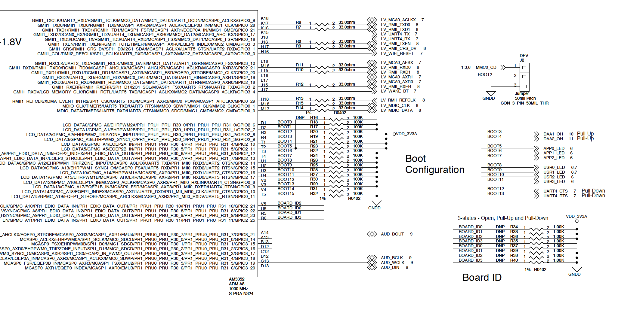
The SYSBOOT[2] pin has a two position jumper on it and the rest of the pins of SYSBOOT [4:0] are either pulled high or low.
So that we get either SYSBOOT[4:0] = 11000b or 11100b depending upon whether the jumper is in position or left open.
SYSBOOT[2] gets pulled low either if there is a SD Card inserted of forced low. If the jumper is left open than it gets pulled high.

Our problem is that the board will boot up only if
(A) We connect a FTDI cable to a USB port (PC or Mac that has been turned on). AND
(B) We have not erased eMMC  AND
(C) We have a valid SD Card (i.e has a FAT32 partition and a Linux partition).

If we disconnect the FTDI cable than it does not boot up.

Any ideas why this happens and how could we rectify this?

Best

Rao

  • Can you please specify how the SD card and the EMMC is connected ie Is SD on MMC0 instance and eMMC on MMC1 instance. Also, is the eMMC flashed with boot images? Which of the 6 UART instances are you using to connect the FTDI connection
    When SYSBOOT is 0x11000 the boot sequence is SPI0, MMC0, USB0, UART0 and for SYSBOOT [4:0] it is MMC1, MMC0, UART0, USB0

    You may want to test which of the 6 pins on the FTDI connection is making the difference to investigate this further and connect pin 1 to GND and see if this setting boot correctly. If it doesnt boot connect RX and TX in loopback mode and then test the setup if it still boots then the issue may be with the control pins.

    Regards,
    Rahul
  • Hi Rahul,
    Thanks....

    My answers below....
    Can you please specify how the SD card and the EMMC is connected ie Is SD on MMC0 instance and eMMC on MMC1 instance.
    >MMC0 pins on the processor are connected to the SD Card connector.
    >MMC1 pins on the processor are connected to the 4GB eMMC device.


    Also, is the eMMC flashed with boot images?
    >No.
    >However - if the eMMC is erased or loaded with a Linux image (tried this as an experiment) than the board will not boot even with the FTDI cable connected.

    Which of the 6 UART instances are you using to connect the FTDI connection.
    >UART0 pins of the processor are connected to FTDI connector.

    I did the experiment you suggested...
    Connected Pin 1 of the FTDI connector to Ground and went sequentially through the remaining pins to see which pin influenced the boot up.
    Turns out this did not effect it. The whole FTDI cable had to be connected.

    I did the loop test as well (Connect RX to TX). But that did not help either.

    Not sure what to do next.

    Best
    Rao
  • Can you post the SYSBOOT section of your schematic?
  • Hi Biser,

    Thanks for helping.

    Here is the SYSBOOT section of our schematic...

    Best

    R

  • One thing to check - some of your SYSBOOT signals are connected to external circuitry as well. Please check that all of these are at the required levels at reset release time.
  • Hi Biser,

    Thanks.

    The BOOT3 and BOOT4 pins are outputs & connected to input pins DAA1_OH & DAA2_OH on the other side. So I am assuming that should be OK?

    Best

    Rao

  • Please measure the signals.
  • Hi Biser

    BOOT3 and BOOT4 both show 3.3V.

    Why would the board boot from the SD Card only if the FTDI cable is connected?

    Best

    Rao

  • What about the BOOT12 and BOOT13 signals? If these are OK too, I cannot say what's happening without having the entire schematics.
  • Hi Biser

    Both BOOT12 and BOOT13 stay at Ground throughout the boot process. After booting up I see that they can go high.

    I can email you the entire schematic but I would rather not post it on the open site. Can you please provide an email address that I can send it to?

    My email address is rgobburu@waagu.com

    Many thanks

    Rao

  • I have sent you a friend request with my e-mail.
  • Something does not seem right to me around the N_RESET signal. Can you try to modify this on a single board to be exactly like the BBB?
  • Hi Biser,

    Some progress on my part....

    If you recall, I had said that we were basically reusing the Beaglebone Black board architecture. It has two 3.3V supplies.
    So on our board as well we have two 3.3V power supplies - referred to as VDD_3V3A and VDD_3V3B.
    The VDD_3V3A is derived from the PMIC, TPS65217C, and powers the Sitara processor etc.
    The VDD_3V3B is derived from a second regulator and powers up the SD Card.

    It seems that the VDD_3V3B is not coming up to the required 3.3V but hovers around 2.4V ~ 2.5V.
    Consequently the SD Card does not function.

    I was able to get the boards to work by shorting the VDD_3V3A and VDD_3V3B - essentially pulling up VDD_3V3B.

    So I have two questions....
    Q1: The PMIC, TPS65217C, is capable of 2A.... so why should there be a secondary regulator for the SD Card?
    Q2: Is there a downside to shorting the two supplies?

    I hope that you can shed some light on this even as we try to get to the root cause and understand why the secondary regulator is not supplying 3.3V.

    Thanks for all your help.

    Rao Gobburu

  • Q1: VDD_3V3A comes from the TPS65217 LDO4, which has a maximum output current of 200mA.
    Q2: Shorting two LDO outputs is a bad practice, as one of them will get overloaded, trying to compensate the other.

    What is the LDO you use for VDD_3V3B? In the BBB design a 500mA LDO is used.