This thread has been locked.

If you have a related question, please click the "Ask a related question" button in the top right corner. The newly created question will be automatically linked to this question.

AM5726: Running PCIe demo in M4 processor

Part Number: AM5726

Good morning. 

We are currently evaluating the Sitara processor for one of our projects. We need to interface with an FPGA through PCIe. Ideally, we would want to run the PCIe software in the M4 so that we can use the available MIPS on the A15 and the C66 to perform other activities. 

From the looks of it, PCIe is indeed supported in the M4 core using Sys/Bios. I was able to generate the example project and compile it through with Code Composer today. However, when I run the code, I get a crash when enabling the PCIe clocks in the PlatformPCIESS1ClockEnable function:

void PlatformPCIESS1ClockEnable(void)
{
    uint32_t regVal;

    /*OCP2SCP1 enables accessing the PCIe PHY serial configuration*/
    HW_WR_FIELD32(SOC_L3INIT_CM_CORE_BASE + CM_L3INIT_OCP2SCP1_CLKCTRL,
                  CM_L3INIT_OCP2SCP1_CLKCTRL_MODULEMODE,
                  CM_L3INIT_OCP2SCP1_CLKCTRL_MODULEMODE_AUTO);

    /*OCP2SCP3 enables accessing the PCIe PHY serial configuration*/
    HW_WR_FIELD32(SOC_L3INIT_CM_CORE_BASE + CM_L3INIT_OCP2SCP3_CLKCTRL,
                  CM_L3INIT_OCP2SCP3_CLKCTRL_MODULEMODE,
                  CM_L3INIT_OCP2SCP3_CLKCTRL_MODULEMODE_AUTO);

    /*PCIeSS CLKSTCTRL SW WakeUp*/
    HW_WR_FIELD32(SOC_L3INIT_CM_CORE_BASE + CM_PCIE_CLKSTCTRL,
                  CM_PCIE_CLKSTCTRL_CLKTRCTRL,
                  CM_PCIE_CLKSTCTRL_CLKTRCTRL_SW_WKUP);

    /*L3 Init PCIeSS1 CLKCTRL SW Enable*/
    HW_WR_FIELD32(SOC_L3INIT_CM_CORE_BASE + CM_PCIE_PCIESS1_CLKCTRL,
                  CM_PCIE_PCIESS1_CLKCTRL_MODULEMODE,
                  CM_PCIE_PCIESS1_CLKCTRL_MODULEMODE_ENABLED);

    while ((HW_RD_REG32(SOC_L3INIT_CM_CORE_BASE + CM_PCIE_PCIESS1_CLKCTRL) &
            CM_PCIE_PCIESS1_CLKCTRL_IDLEST_MASK) !=
           CM_PCIE_PCIESS1_CLKCTRL_IDLEST_FUNC)
    {
        ;
    }

    /*Enable PCIe PHY optional clk*/
    regVal = HW_RD_REG32(SOC_L3INIT_CM_CORE_BASE + CM_PCIE_PCIESS1_CLKCTRL);

    HW_SET_FIELD(regVal, CM_PCIE_PCIESS1_CLKCTRL_OPTFCLKEN_PCIEPHY_CLK_DIV,
                 CM_PCIE_PCIESS1_CLKCTRL_OPTFCLKEN_PCIEPHY_CLK_DIV_FCLK_EN);

    HW_SET_FIELD(regVal, CM_PCIE_PCIESS1_CLKCTRL_OPTFCLKEN_PCIEPHY_CLK,
                 CM_PCIE_PCIESS1_CLKCTRL_OPTFCLKEN_PCIEPHY_CLK_FCLK_EN);

    HW_SET_FIELD(regVal, CM_PCIE_PCIESS1_CLKCTRL_OPTFCLKEN_32KHZ,
                 CM_PCIE_PCIESS1_CLKCTRL_OPTFCLKEN_32KHZ_FCLK_EN);

    HW_WR_REG32(SOC_L3INIT_CM_CORE_BASE + CM_PCIE_PCIESS1_CLKCTRL, regVal);
}

I suspect this is crashing because the M4 doesn't have access to the registers it is trying to write to. 

My question is how can I make these registers (and all other required PCIe memory region) available on the M4?

Best Regards, 

- David

  • David,

    What hardware are you trying to test this on ? Are you using the AM572x IDK or custom hardware ? Please check the important note added here regarding modifying the PCIe cable to avoid the clock driver in the SOC. This may be the root cause of the issue that you are seeing:
    processors.wiki.ti.com/.../Processor_SDK_RTOS_PCIe

    Refer to this wiki for full details regarding the modification:
    processors.wiki.ti.com/.../PCIe_CableMod

    Regards,
    Rahul
  • I am testing this on the evmAM572x. The evm is connected to an Altera Cyclone V FPGA using a PCB.
    In Linux, we see the Altera FPGA being properly detected when runing lspci. So we know the PCIe stuff is working.

    Now, for architecture reasons, we would like to use one of the M4 cores for the PCIe driver.

    Note that we want to keep Linux running on the A15 cores.

    Regards,
    - David
  • Ok, I have managed to get pass this "crash" by converting the Physical address to a virtual address.

    I have a resource file defining the L4_CFG physical and virtual addresses (based on the IPC examples). So, once I converted all access to 0x4A00_0000 addresses to 0x6A00_0000 addresses using Resource_physToVirt the clock got configured correctly. 

    However, it now crashes / hangs in the Pcie_setInterfaceMode.

    I have added the different memory section for PCIe in my custom resource table already but that doesn't seem to help. Do I need to do something else?

    As a reference, here is my custom table: 

    /*
     * Copyright (c) 2012-2014, Texas Instruments Incorporated
     * All rights reserved.
     *
     * Redistribution and use in source and binary forms, with or without
     * modification, are permitted provided that the following conditions
     * are met:
     *
     * *  Redistributions of source code must retain the above copyright
     *    notice, this list of conditions and the following disclaimer.
     *
     * *  Redistributions in binary form must reproduce the above copyright
     *    notice, this list of conditions and the following disclaimer in the
     *    documentation and/or other materials provided with the distribution.
     *
     * *  Neither the name of Texas Instruments Incorporated nor the names of
     *    its contributors may be used to endorse or promote products derived
     *    from this software without specific prior written permission.
     *
     * THIS SOFTWARE IS PROVIDED BY THE COPYRIGHT HOLDERS AND CONTRIBUTORS "AS IS"
     * AND ANY EXPRESS OR IMPLIED WARRANTIES, INCLUDING, BUT NOT LIMITED TO,
     * THE IMPLIED WARRANTIES OF MERCHANTABILITY AND FITNESS FOR A PARTICULAR
     * PURPOSE ARE DISCLAIMED. IN NO EVENT SHALL THE COPYRIGHT OWNER OR
     * CONTRIBUTORS BE LIABLE FOR ANY DIRECT, INDIRECT, INCIDENTAL, SPECIAL,
     * EXEMPLARY, OR CONSEQUENTIAL DAMAGES (INCLUDING, BUT NOT LIMITED TO,
     * PROCUREMENT OF SUBSTITUTE GOODS OR SERVICES; LOSS OF USE, DATA, OR PROFITS;
     * OR BUSINESS INTERRUPTION) HOWEVER CAUSED AND ON ANY THEORY OF LIABILITY,
     * WHETHER IN CONTRACT, STRICT LIABILITY, OR TORT (INCLUDING NEGLIGENCE OR
     * OTHERWISE) ARISING IN ANY WAY OUT OF THE USE OF THIS SOFTWARE,
     * EVEN IF ADVISED OF THE POSSIBILITY OF SUCH DAMAGE.
     */
    
    /*
     *  ======== rsc_table_vayu_ipu.h ========
     *
     *  Define the resource table entries for all IPU cores. This will be
     *  incorporated into corresponding base images, and used by the remoteproc
     *  on the host-side to allocated/reserve resources.
     *
     */
    
    #ifndef _RSC_TABLE_VAYU_IPU_H_
    #define _RSC_TABLE_VAYU_IPU_H_
    
    #include <ti/ipc/remoteproc/rsc_types.h>
    
    /* IPU Memory Map */
    #define L4_DRA7XX_BASE          0x4A000000
    
    /* L4_CFG & L4_WKUP */
    #define L4_PERIPHERAL_L4CFG     (L4_DRA7XX_BASE)
    #define IPU_PERIPHERAL_L4CFG    0x6A000000
    
    #define L4_PERIPHERAL_L4PER1    0x48000000
    #define IPU_PERIPHERAL_L4PER1   0x68000000
    
    #define L4_PERIPHERAL_L4PER2    0x48400000
    #define IPU_PERIPHERAL_L4PER2   0x68400000
    
    #define L4_PERIPHERAL_L4PER3    0x48800000
    #define IPU_PERIPHERAL_L4PER3   0x68800000
    
    #define L4_PERIPHERAL_L4EMU     0x54000000
    #define IPU_PERIPHERAL_L4EMU    0x74000000
    
    #define L3_PERIPHERAL_DMM       0x4E000000
    #define IPU_PERIPHERAL_DMM      0x6E000000
    
    #define L3_IVAHD_CONFIG         0x5A000000
    #define IPU_IVAHD_CONFIG        0x7A000000
    
    #define L3_IVAHD_SL2            0x5B000000
    #define IPU_IVAHD_SL2           0x7B000000
    
    #define L3_TILER_MODE_0_1       0x60000000
    #define IPU_TILER_MODE_0_1      0xA0000000
    
    #define L3_TILER_MODE_2         0x70000000
    #define IPU_TILER_MODE_2        0xB0000000
    
    #define L3_TILER_MODE_3         0x78000000
    #define IPU_TILER_MODE_3        0xB8000000
    
    #define IPU_MEM_TEXT            0x0
    #define IPU_MEM_DATA            0x80000000
    
    #define IPU_MEM_IOBUFS          0x90000000
    
    #define IPU_MEM_IPC_DATA        0x9F000000
    #define IPU_MEM_IPC_VRING       0x60000000
    #define IPU_MEM_RPMSG_VRING0    0x60000000
    #define IPU_MEM_RPMSG_VRING1    0x60004000
    #define IPU_MEM_VRING_BUFS0     0x60040000
    #define IPU_MEM_VRING_BUFS1     0x60080000
    
    #define IPU_MEM_IPC_VRING_SIZE  SZ_1M
    #define IPU_MEM_IPC_DATA_SIZE   SZ_1M
    
    #if defined(VAYU_IPU_1)
    #define IPU_MEM_TEXT_SIZE       (SZ_1M)
    #elif defined(VAYU_IPU_2)
    #define IPU_MEM_TEXT_SIZE       (SZ_1M * 6)
    #endif
    
    #if defined(VAYU_IPU_1)
    #define IPU_MEM_DATA_SIZE       (SZ_1M * 5)
    #elif defined(VAYU_IPU_2)
    #define IPU_MEM_DATA_SIZE       (SZ_1M * 48)
    #endif
    
    #define IPU_MEM_IOBUFS_SIZE     (SZ_1M * 90)
    
    /*
     * Assign fixed RAM addresses to facilitate a fixed MMU table.
     * PHYS_MEM_IPC_VRING & PHYS_MEM_IPC_DATA MUST be together.
     */
    /* See CMA BASE addresses in Linux side: arch/arm/mach-omap2/remoteproc.c */
    #if defined(VAYU_IPU_1)
    #define PHYS_MEM_IPC_VRING      0x9D000000
    #elif defined (VAYU_IPU_2)
    #define PHYS_MEM_IPC_VRING      0x95800000
    #endif
    
    #define PHYS_MEM_IOBUFS         0xBA300000
    
    #define PCIE_SS1_CFG_SPACE      0x20000000
    //#define PCIE_SS1_CFG_SPACE_VIRT 0xC0000000
    #define PCIE_SS1_CFG_SPACE_VIRT PCIE_SS1_CFG_SPACE
    #define PCIE_SS2_CFG_SPACE      0x30000000
    //#define PCIE_SS2_CFG_SPACE_VIRT 0xD0000000
    #define PCIE_SS2_CFG_SPACE_VIRT PCIE_SS2_CFG_SPACE
    #define PCIE_SS_CFG_SPACE_SIZE  SZ_256M
    
    #define PCIE_SS1_CFG_REGS       0x51000000
    //#define PCIE_SS1_CFG_REGS_VIRT  0xE0000000
    #define PCIE_SS1_CFG_REGS_VIRT  PCIE_SS1_CFG_REGS
    #define PCIE_SS2_CFG_REGS       0x51800000
    //#define PCIE_SS2_CFG_REGS_VIRT  0xE0800000
    #define PCIE_SS2_CFG_REGS_VIRT  PCIE_SS2_CFG_REGS
    #define PCIE_SS_CFG_REGS_SIZE   SZ_8M
    
    /*
     * Sizes of the virtqueues (expressed in number of buffers supported,
     * and must be power of 2)
     */
    #define IPU_RPMSG_VQ0_SIZE      256
    #define IPU_RPMSG_VQ1_SIZE      256


    /* flip up bits whose indices represent features we support */
    #define RPMSG_IPU_C0_FEATURES   1
    
    struct my_resource_table {
        struct resource_table base;
    
        UInt32 offset[22];  /* Should match 'num' in actual definition */
    
        /* rpmsg vdev entry */
        struct fw_rsc_vdev rpmsg_vdev;
        struct fw_rsc_vdev_vring rpmsg_vring0;
        struct fw_rsc_vdev_vring rpmsg_vring1;
    
        /* text carveout entry */
        struct fw_rsc_carveout text_cout;
    
        /* data carveout entry */
        struct fw_rsc_carveout data_cout;
    
        /* ipcdata carveout entry */
        struct fw_rsc_carveout ipcdata_cout;
    
        /* trace entry */
        struct fw_rsc_trace trace;
    
        /* devmem entry */
        struct fw_rsc_devmem devmem0;
    
        /* devmem entry */
        struct fw_rsc_devmem devmem1;
    
        /* devmem entry */
        struct fw_rsc_devmem devmem2;
    
        /* devmem entry */
        struct fw_rsc_devmem devmem3;
    
        /* devmem entry */
        struct fw_rsc_devmem devmem4;
    
        /* devmem entry */
        struct fw_rsc_devmem devmem5;
    
        /* devmem entry */
        struct fw_rsc_devmem devmem6;
    
        /* devmem entry */
        struct fw_rsc_devmem devmem7;
    
        /* devmem entry */
        struct fw_rsc_devmem devmem8;
    
        /* devmem entry */
        struct fw_rsc_devmem devmem9;
    
        /* devmem entry */
        struct fw_rsc_devmem devmem10;
    
        /* devmem entry */
        struct fw_rsc_devmem devmem11;
    
        /* devmem entry */
        struct fw_rsc_devmem devmem12;
    
        /* devmem entry */
        struct fw_rsc_devmem devmem13;
        /* devmem entry */
        struct fw_rsc_devmem devmem14;
        /* devmem entry */
        struct fw_rsc_devmem devmem15;
        /* devmem entry */
        struct fw_rsc_devmem devmem16;
    };
    
     extern char ti_trace_SysMin_Module_State_0_outbuf__A;
    #define TRACEBUFADDR (UInt32)&ti_trace_SysMin_Module_State_0_outbuf__A
    
    #pragma DATA_SECTION(ti_ipc_remoteproc_ResourceTable, ".resource_table")
    #pragma DATA_ALIGN(ti_ipc_remoteproc_ResourceTable, 4096)
    
    struct my_resource_table ti_ipc_remoteproc_ResourceTable = {
        1,      /* we're the first version that implements this */
        22,     /* number of entries in the table */
        0, 0,   /* reserved, must be zero */
        /* offsets to entries */
        {
            offsetof(struct my_resource_table, rpmsg_vdev),
            offsetof(struct my_resource_table, text_cout),
            offsetof(struct my_resource_table, data_cout),
            offsetof(struct my_resource_table, ipcdata_cout),
            offsetof(struct my_resource_table, trace),
            offsetof(struct my_resource_table, devmem0),
            offsetof(struct my_resource_table, devmem1),
            offsetof(struct my_resource_table, devmem2),
            offsetof(struct my_resource_table, devmem3),
            offsetof(struct my_resource_table, devmem4),
            offsetof(struct my_resource_table, devmem5),
            offsetof(struct my_resource_table, devmem6),
            offsetof(struct my_resource_table, devmem7),
            offsetof(struct my_resource_table, devmem8),
            offsetof(struct my_resource_table, devmem9),
            offsetof(struct my_resource_table, devmem10),
            offsetof(struct my_resource_table, devmem11),
            offsetof(struct my_resource_table, devmem12),
            offsetof(struct my_resource_table, devmem13),
            offsetof(struct my_resource_table, devmem14),
            offsetof(struct my_resource_table, devmem15),
            offsetof(struct my_resource_table, devmem16),
        },
    
        /* rpmsg vdev entry */
        {
            TYPE_VDEV, VIRTIO_ID_RPMSG, 0,
            RPMSG_IPU_C0_FEATURES, 0, 0, 0, 2, { 0, 0 },
            /* no config data */
        },
        /* the two vrings */
        { IPU_MEM_RPMSG_VRING0, 4096, IPU_RPMSG_VQ0_SIZE, 1, 0 },
        { IPU_MEM_RPMSG_VRING1, 4096, IPU_RPMSG_VQ1_SIZE, 2, 0 },
    
        {
            TYPE_CARVEOUT,
            IPU_MEM_TEXT, 0,
            IPU_MEM_TEXT_SIZE, 0, 0, "IPU_MEM_TEXT",
        },
    
        {
            TYPE_CARVEOUT,
            IPU_MEM_DATA, 0,
            IPU_MEM_DATA_SIZE, 0, 0, "IPU_MEM_DATA",
        },
    
        {
            TYPE_CARVEOUT,
            IPU_MEM_IPC_DATA, 0,
            IPU_MEM_IPC_DATA_SIZE, 0, 0, "IPU_MEM_IPC_DATA",
        },
    
        {
            TYPE_TRACE, TRACEBUFADDR, 0x8000, 0, "trace:sysm3",
        },
    
        {
            TYPE_DEVMEM,
            IPU_MEM_IPC_VRING, PHYS_MEM_IPC_VRING,
            IPU_MEM_IPC_VRING_SIZE, 0, 0, "IPU_MEM_IPC_VRING",
        },
    
        {
            TYPE_DEVMEM,
            IPU_MEM_IOBUFS, PHYS_MEM_IOBUFS,
            IPU_MEM_IOBUFS_SIZE, 0, 0, "IPU_MEM_IOBUFS",
        },
    
        {
            TYPE_DEVMEM,
            IPU_TILER_MODE_0_1, L3_TILER_MODE_0_1,
            SZ_256M, 0, 0, "IPU_TILER_MODE_0_1",
        },
    
        {
            TYPE_DEVMEM,
            IPU_TILER_MODE_2, L3_TILER_MODE_2,
            SZ_128M, 0, 0, "IPU_TILER_MODE_2",
        },
    
        {
            TYPE_DEVMEM,
            IPU_TILER_MODE_3, L3_TILER_MODE_3,
            SZ_128M, 0, 0, "IPU_TILER_MODE_3",
        },
    
        {
            TYPE_DEVMEM,
            IPU_PERIPHERAL_L4CFG, L4_PERIPHERAL_L4CFG,
            SZ_16M, 0, 0, "IPU_PERIPHERAL_L4CFG",
        },
    
        {
            TYPE_DEVMEM,
            IPU_PERIPHERAL_L4PER1, L4_PERIPHERAL_L4PER1,
            SZ_2M, 0, 0, "IPU_PERIPHERAL_L4PER1",
        },
    
        {
            TYPE_DEVMEM,
            IPU_PERIPHERAL_L4PER2, L4_PERIPHERAL_L4PER2,
            SZ_4M, 0, 0, "IPU_PERIPHERAL_L4PER2",
        },
    
        {
            TYPE_DEVMEM,
            IPU_PERIPHERAL_L4PER3, L4_PERIPHERAL_L4PER3,
            SZ_8M, 0, 0, "IPU_PERIPHERAL_L4PER3",
        },
    
        {
            TYPE_DEVMEM,
            IPU_PERIPHERAL_L4EMU, L4_PERIPHERAL_L4EMU,
            SZ_16M, 0, 0, "IPU_PERIPHERAL_L4EMU",
        },
    
        {
            TYPE_DEVMEM,
            IPU_IVAHD_CONFIG, L3_IVAHD_CONFIG,
            SZ_16M, 0, 0, "IPU_IVAHD_CONFIG",
        },
    
        {
            TYPE_DEVMEM,
            IPU_IVAHD_SL2, L3_IVAHD_SL2,
            SZ_16M, 0, 0, "IPU_IVAHD_SL2",
        },
    
        {
            TYPE_DEVMEM,
            IPU_PERIPHERAL_DMM, L3_PERIPHERAL_DMM,
            SZ_1M, 0, 0, "IPU_PERIPHERAL_DMM",
        },
    
        {
            TYPE_DEVMEM,
            PCIE_SS1_CFG_SPACE_VIRT, PCIE_SS1_CFG_SPACE,
            PCIE_SS_CFG_SPACE_SIZE, 0, 0, "PCIE_SS1_CFG_SPACE",
        },
        {
            TYPE_DEVMEM,
            PCIE_SS2_CFG_SPACE_VIRT, PCIE_SS2_CFG_SPACE,
            PCIE_SS_CFG_SPACE_SIZE, 0, 0, "PCIE_SS2_CFG_SPACE",
        },
        {
            TYPE_DEVMEM,
            PCIE_SS1_CFG_REGS_VIRT, PCIE_SS1_CFG_REGS,
            SZ_1M, 0, 0, "PCIE_SS1_CFG_REGS",
        },
        {
            TYPE_DEVMEM,
            PCIE_SS2_CFG_REGS_VIRT, PCIE_SS2_CFG_REGS,
            PCIE_SS_CFG_REGS_SIZE, 0, 0, "PCIE_SS2_CFG_REGS",
        },
    };
    
    #endif /* _RSC_TABLE_VAYU_IPU_H_ */
    

    Regards, 

    - David

  • ,

    Can you provide me with an update on this?
    I am still struggling in getting this to work.
    I have disabled the PCIe module in the linux kernel / DTB for the EVM to make sure it doesn't conflict with the M4 configuration. Howver, it still crashes in the pcie_setInterfaceMode function.

    Regards,
    - David
  • David,

    Sorry about the delayed response on this thread. I have looped in some of my colleagues who may be able help with this issue.
    In the meantime can you provide the crash log to help us determine what may be the root cause of the issue.

    On the M4 is there any board initialization(clocking, pinmuxing, etc) being done to access the PCIE module.

    Regards,
    Rahul
  • Hi Rahul,

    I will provide the crash dump later on today.

    With regards to the board initialization, I have done some (basically copying what was done in the sample code).

    Board_initCfg boardCfg;
    boardCfg = BOARD_INIT_UNLOCK_MMR
    ifndef IO_CONSOLE
                   | BOARD_INIT_UART_STDIO
                   | BOARD_INIT_MODULE_CLOCK
    #endif
    #if !defined(DEVICE_K2E) && !defined(SOC_K2E)
                   | BOARD_INIT_PINMUX_CONFIG
    #endif
        ;
    Board_init(boardCfg);

    However, it doesn't help.

    So, basically, in my test I have Linux running on the A15. I have disabled the PCIe driver in the kernel. The M4 app is pushed using the remoteproc / rpmsg drivers. I want the M4 application to use  the PCIe module.

    Can the board initialization be done on the Linux side?

    - David

  • David,

    Are you able to run PCIE example standalone on M4 (don't run Linux on A15) as it is?

    If you have to run Linux on A15 but disabled PCIE driver in Linux kernel and you had done some work to add physical to virtual address conversion and resolved the clock domain crash issue, then you need to do the same thing for PCIE controller domain: 0x5100_0000 for PCIE SS1 and 0x5180_0000 for PCIE SS2. The Pcie_setInterfaceMode API tries to access register 0x5100_2100 or 0x5180_2100.

    Regards, Eric
  • Hi Eric,

    Thanks for the response.

    I have actually figured this out 30 minutes ago. I found out about the bit-banding feature of the M4 where we need to translate all memory access in the 0x4000 0000 to 0x6000 0000 by 0x2000 0000. I haven't tried it yet.

    Now, I want back to the standalone PCIE example on the M4. Currently, I am getting a link up event and I am trying to enumerate the PCIe  buses  (the M4 will be running as root complex). I had an enumerate procedure for a C66x working on a KeyStone II device but I have to adapt it to work on the Sitara processor. But it needs to be adapted since the pcieCfgTransReg_t is not supported on the AM572x processor. 

    I read in the TRM (24.9.4.8.2.2) that the enumeration process can be done with an ATU outbound region but I don't understand yet how that works. I want to get that to work before moving back to the combined IPC+PCIe example. 

    Did I read the information found in the TRM correctly?

    Is there any examples that uses the ATU to perform enumeration process?

    Best Regards,

    - David

  • I just got enumeration going on the M4 with the standalone application.
    I will try the same on the M4 while running Linux on the A15.

    I will let you know of the results.

    Regards,
    - David
  • David,

    Thanks for the note, good progress! The pcieCfgTransReg_t API only supports on V0 hardware, that is Keystone device. There is no such for V1 device like AM57x. Even with such API on V0, we don't have any example code to send CFG TLP over PCIE bus. The RTOS is very simple process compared to OS like Linux. The RTOS example code relies on the configuration on both-end by itself, then enable the link training. In other word, it is more of a link training than an full enumeration process.

    We have many customers used RTOS code to talk between Keystone device or Sitara device to FPGA, and it worked. So you may not need to do the same configuration with pcieCfgTransReg_t. If you have to, 24.9.4.8.2.2 is the right location.

    Regards, Eric
  • Hi Eric,

    I can't get the code to read the remote vendor and device id.

    Also, when I try to read @ address 0x2001 0000 and beyond, I get an access violation in the M4:

    [0][     11.788] [t=0x00000001:1f3ca0ab] ti.sysbios.family.arm.m3.Hwi: ERROR: line 1094: E_hardFault: FORCED
    [0][     11.788] ti.sysbios.family.arm.m3.Hwi: line 1094: E_hardFault: FORCED
    [0][     11.788] [t=0x00000001:1f3f7e61] ti.sysbios.family.arm.m3.Hwi: ERROR: line 1171: E_busFault: PRECISERR: Immediate Bus Fault, exact addr known, address: 20010000
    [0][     11.788] ti.sysbios.family.arm.m3.Hwi: line 1171: E_busFault: PRECISERR: Immediate Bus Fault, exact addr known, address: 20010000
    [0][     11.788] Exception occurred in background thread at PC = 0x0001800a.
    [0][     11.788] Core 0: Exception occurred in ThreadType_Task.
    [0][     11.788] Task name: {empty-instance-name}, handle: 0x80000040.
    [0][     11.788] Task stack base: 0x80000090.
    [0][     11.788] Task stack size: 0x9000.
    [0][     11.788] R0 = 0x20010000  R8  = 0x71001000
    [0][     11.788] R1 = 0x80009038  R9  = 0x20010700
    [0][     11.788] R2 = 0x20000000  R10 = 0x00000001
    [0][     11.788] R3 = 0x00000004  R11 = 0x80104684
    [0][     11.788] R4 = 0x80008c2c  R12 = 0x71000700
    [0][     11.788] R5 = 0x20010000  SP(R13) = 0x80008bb0
    [0][     11.788] R6 = 0x80104edc  LR(R14) = 0x00009203
    [0][     11.788] R7 = 0x00000000  PC(R15) = 0x0001800a
    [0][     11.788] PSR = 0x61000000
    [0][     11.788] ICSR = 0x00438803
    [0][     11.788] MMFSR = 0x00
    [0][     11.788] BFSR = 0x82
    [0][     11.788] UFSR = 0x0000
    [0][     11.788] HFSR = 0x40000000
    [0][     11.788] DFSR = 0x00000000
    [0][     11.788] MMAR = 0x20010000
    [0][     11.788] BFAR = 0x20010000
    [0][     11.788] AFSR = 0x00000000
    [0][     11.788] Terminating execution...
    

    I have the following custom resource definition which maps 0x20000000 for 256 MB. So, I don't know why this is failing...

    /*
     * Copyright (c) 2012-2014, Texas Instruments Incorporated
     * All rights reserved.
     *
     * Redistribution and use in source and binary forms, with or without
     * modification, are permitted provided that the following conditions
     * are met:
     *
     * *  Redistributions of source code must retain the above copyright
     *    notice, this list of conditions and the following disclaimer.
     *
     * *  Redistributions in binary form must reproduce the above copyright
     *    notice, this list of conditions and the following disclaimer in the
     *    documentation and/or other materials provided with the distribution.
     *
     * *  Neither the name of Texas Instruments Incorporated nor the names of
     *    its contributors may be used to endorse or promote products derived
     *    from this software without specific prior written permission.
     *
     * THIS SOFTWARE IS PROVIDED BY THE COPYRIGHT HOLDERS AND CONTRIBUTORS "AS IS"
     * AND ANY EXPRESS OR IMPLIED WARRANTIES, INCLUDING, BUT NOT LIMITED TO,
     * THE IMPLIED WARRANTIES OF MERCHANTABILITY AND FITNESS FOR A PARTICULAR
     * PURPOSE ARE DISCLAIMED. IN NO EVENT SHALL THE COPYRIGHT OWNER OR
     * CONTRIBUTORS BE LIABLE FOR ANY DIRECT, INDIRECT, INCIDENTAL, SPECIAL,
     * EXEMPLARY, OR CONSEQUENTIAL DAMAGES (INCLUDING, BUT NOT LIMITED TO,
     * PROCUREMENT OF SUBSTITUTE GOODS OR SERVICES; LOSS OF USE, DATA, OR PROFITS;
     * OR BUSINESS INTERRUPTION) HOWEVER CAUSED AND ON ANY THEORY OF LIABILITY,
     * WHETHER IN CONTRACT, STRICT LIABILITY, OR TORT (INCLUDING NEGLIGENCE OR
     * OTHERWISE) ARISING IN ANY WAY OUT OF THE USE OF THIS SOFTWARE,
     * EVEN IF ADVISED OF THE POSSIBILITY OF SUCH DAMAGE.
     */
    
    /*
     *  ======== rsc_table_vayu_ipu.h ========
     *
     *  Define the resource table entries for all IPU cores. This will be
     *  incorporated into corresponding base images, and used by the remoteproc
     *  on the host-side to allocated/reserve resources.
     *
     */
    
    #ifndef USE_DEFAULT_TABLE
    
    #ifndef _RSC_TABLE_VAYU_IPU_H_
    #define _RSC_TABLE_VAYU_IPU_H_
    
    #include <ti/ipc/remoteproc/rsc_types.h>
    
    /* IPU Memory Map */
    #define L4_DRA7XX_BASE          0x4A000000
    
    /* L4_CFG & L4_WKUP */
    #define L4_PERIPHERAL_L4CFG     (L4_DRA7XX_BASE)
    #define IPU_PERIPHERAL_L4CFG    0x6A000000
    
    #define L4_PERIPHERAL_L4PER1    0x48000000
    #define IPU_PERIPHERAL_L4PER1   0x68000000
    
    #define L4_PERIPHERAL_L4PER2    0x48400000
    #define IPU_PERIPHERAL_L4PER2   0x68400000
    
    #define L4_PERIPHERAL_L4PER3    0x48800000
    #define IPU_PERIPHERAL_L4PER3   0x68800000
    
    #define L4_PERIPHERAL_L4EMU     0x54000000
    #define IPU_PERIPHERAL_L4EMU    0x74000000
    
    #define L3_PERIPHERAL_DMM       0x4E000000
    #define IPU_PERIPHERAL_DMM      0x6E000000
    
    #define L3_IVAHD_CONFIG         0x5A000000
    #define IPU_IVAHD_CONFIG        0x7A000000
    
    #define L3_IVAHD_SL2            0x5B000000
    #define IPU_IVAHD_SL2           0x7B000000
    
    #define L3_TILER_MODE_0_1       0x60000000
    #define IPU_TILER_MODE_0_1      0xA0000000
    
    #define L3_TILER_MODE_2         0x70000000
    #define IPU_TILER_MODE_2        0xB0000000
    
    #define L3_TILER_MODE_3         0x78000000
    #define IPU_TILER_MODE_3        0xB8000000
    
    #define IPU_MEM_TEXT            0x0
    #define IPU_MEM_DATA            0x80000000
    
    #define IPU_MEM_IOBUFS          0x90000000
    
    #define IPU_MEM_IPC_DATA        0x9F000000
    #define IPU_MEM_IPC_VRING       0x60000000
    #define IPU_MEM_RPMSG_VRING0    0x60000000
    #define IPU_MEM_RPMSG_VRING1    0x60004000
    #define IPU_MEM_VRING_BUFS0     0x60040000
    #define IPU_MEM_VRING_BUFS1     0x60080000
    
    #define IPU_MEM_IPC_VRING_SIZE  SZ_1M
    #define IPU_MEM_IPC_DATA_SIZE   SZ_1M
    
    #if defined(VAYU_IPU_1)
    #define IPU_MEM_TEXT_SIZE       (SZ_1M)
    #elif defined(VAYU_IPU_2)
    #define IPU_MEM_TEXT_SIZE       (SZ_1M * 6)
    #endif
    
    #if defined(VAYU_IPU_1)
    #define IPU_MEM_DATA_SIZE       (SZ_1M * 5)
    #elif defined(VAYU_IPU_2)
    #define IPU_MEM_DATA_SIZE       (SZ_1M * 48)
    #endif
    
    #define IPU_MEM_IOBUFS_SIZE     (SZ_1M * 90)
    
    /*
     * Assign fixed RAM addresses to facilitate a fixed MMU table.
     * PHYS_MEM_IPC_VRING & PHYS_MEM_IPC_DATA MUST be together.
     */
    /* See CMA BASE addresses in Linux side: arch/arm/mach-omap2/remoteproc.c */
    #if defined(VAYU_IPU_1)
    #define PHYS_MEM_IPC_VRING      0x9D000000
    #elif defined (VAYU_IPU_2)
    #define PHYS_MEM_IPC_VRING      0x95800000
    #endif
    
    #define PHYS_MEM_IOBUFS         0xBA300000
    
    #define PCIE_SS1_CFG_SPACE      0x20000000
    #define PCIE_SS1_CFG_SPACE_VIRT PCIE_SS1_CFG_SPACE
    
    #define PCIE_SS2_CFG_SPACE      0x30000000
    #define PCIE_SS2_CFG_SPACE_VIRT PCIE_SS2_CFG_SPACE
    
    #define PCIE_RESERVED_PHYS       0x52000000
    #define PCIE_RESERVED_VIRT       (0x52000000 + 0x20000000)
    #define PCIE_RESERVED_SIZE       SZ_32M
    
    #define PCIE_SS_CFG_SPACE_SIZE  SZ_256M
    
    #define PCIE_SS1_CFG_REGS       0x51000000
    #define PCIE_SS1_CFG_REGS_VIRT  (PCIE_SS1_CFG_REGS + 0x20000000)
    #define PCIE_SS2_CFG_REGS       0x51800000
    #define PCIE_SS2_CFG_REGS_VIRT  (PCIE_SS2_CFG_REGS + 0x20000000)
    #define PCIE_SS_CFG_REGS_SIZE   SZ_8M
    
    /*
     * Sizes of the virtqueues (expressed in number of buffers supported,
     * and must be power of 2)
     */
    #define IPU_RPMSG_VQ0_SIZE      256
    #define IPU_RPMSG_VQ1_SIZE      256


    /* flip up bits whose indices represent features we support */
    #define RPMSG_IPU_C0_FEATURES   1
    
    struct my_resource_table {
        struct resource_table base;
    
        UInt32 offset[22];  /* Should match 'num' in actual definition */
    
        /* rpmsg vdev entry */
        struct fw_rsc_vdev rpmsg_vdev;
        struct fw_rsc_vdev_vring rpmsg_vring0;
        struct fw_rsc_vdev_vring rpmsg_vring1;
    
        /* text carveout entry */
        struct fw_rsc_carveout text_cout;
    
        /* data carveout entry */
        struct fw_rsc_carveout data_cout;
    
        /* ipcdata carveout entry */
        struct fw_rsc_carveout ipcdata_cout;
    
        /* trace entry */
        struct fw_rsc_trace trace;
    
        /* devmem entry */
        struct fw_rsc_devmem devmem0;
    
        /* devmem entry */
        struct fw_rsc_devmem devmem1;
    
        /* devmem entry */
        struct fw_rsc_devmem devmem2;
    
        /* devmem entry */
        struct fw_rsc_devmem devmem3;
    
        /* devmem entry */
        struct fw_rsc_devmem devmem4;
    
        /* devmem entry */
        struct fw_rsc_devmem devmem5;
    
        /* devmem entry */
        struct fw_rsc_devmem devmem6;
    
        /* devmem entry */
        struct fw_rsc_devmem devmem7;
    
        /* devmem entry */
        struct fw_rsc_devmem devmem8;
    
        /* devmem entry */
        struct fw_rsc_devmem devmem9;
    
        /* devmem entry */
        struct fw_rsc_devmem devmem10;
    
        /* devmem entry */
        struct fw_rsc_devmem devmem11;
    
        /* devmem entry */
        struct fw_rsc_devmem devmem12;
    
        /* devmem entry */
        struct fw_rsc_devmem devmem13;
        /* devmem entry */
        struct fw_rsc_devmem devmem14;
        /* devmem entry */
        struct fw_rsc_devmem devmem15;
        /* devmem entry */
        struct fw_rsc_devmem devmem16;
    };
    
     extern char ti_trace_SysMin_Module_State_0_outbuf__A;
    #define TRACEBUFADDR (UInt32)&ti_trace_SysMin_Module_State_0_outbuf__A
    
    #pragma DATA_SECTION(ti_ipc_remoteproc_ResourceTable, ".resource_table")
    #pragma DATA_ALIGN(ti_ipc_remoteproc_ResourceTable, 4096)
    
    struct my_resource_table ti_ipc_remoteproc_ResourceTable = {
        1,      /* we're the first version that implements this */
        22,     /* number of entries in the table */
        0, 0,   /* reserved, must be zero */
        /* offsets to entries */
        {
            offsetof(struct my_resource_table, rpmsg_vdev),
            offsetof(struct my_resource_table, text_cout),
            offsetof(struct my_resource_table, data_cout),
            offsetof(struct my_resource_table, ipcdata_cout),
            offsetof(struct my_resource_table, trace),
            offsetof(struct my_resource_table, devmem0),
            offsetof(struct my_resource_table, devmem1),
            offsetof(struct my_resource_table, devmem2),
            offsetof(struct my_resource_table, devmem3),
            offsetof(struct my_resource_table, devmem4),
            offsetof(struct my_resource_table, devmem5),
            offsetof(struct my_resource_table, devmem6),
            offsetof(struct my_resource_table, devmem7),
            offsetof(struct my_resource_table, devmem8),
            offsetof(struct my_resource_table, devmem9),
            offsetof(struct my_resource_table, devmem10),
            offsetof(struct my_resource_table, devmem11),
            offsetof(struct my_resource_table, devmem12),
            offsetof(struct my_resource_table, devmem13),
            offsetof(struct my_resource_table, devmem14),
            offsetof(struct my_resource_table, devmem15),
            offsetof(struct my_resource_table, devmem16),
        },
    
        /* rpmsg vdev entry */
        {
            TYPE_VDEV, VIRTIO_ID_RPMSG, 0,
            RPMSG_IPU_C0_FEATURES, 0, 0, 0, 2, { 0, 0 },
            /* no config data */
        },
        /* the two vrings  text_cout + */
        { IPU_MEM_RPMSG_VRING0, 4096, IPU_RPMSG_VQ0_SIZE, 1, 0 },
        { IPU_MEM_RPMSG_VRING1, 4096, IPU_RPMSG_VQ1_SIZE, 2, 0 },
    
        {
            TYPE_CARVEOUT,
            IPU_MEM_TEXT, 0,
            IPU_MEM_TEXT_SIZE, 0, 0, "IPU_MEM_TEXT",
        },
    
        {
            TYPE_CARVEOUT,
            IPU_MEM_DATA, 0,
            IPU_MEM_DATA_SIZE, 0, 0, "IPU_MEM_DATA",
        },
    
        {
            TYPE_CARVEOUT,
            IPU_MEM_IPC_DATA, 0,
            IPU_MEM_IPC_DATA_SIZE, 0, 0, "IPU_MEM_IPC_DATA",
        },
    
        {
            TYPE_TRACE, TRACEBUFADDR, 0x8000, 0, "trace:sysm3",
        },
    
        {
            TYPE_DEVMEM,
            IPU_MEM_IPC_VRING, PHYS_MEM_IPC_VRING,
            IPU_MEM_IPC_VRING_SIZE, 0, 0, "IPU_MEM_IPC_VRING",
        },
    
        {
            TYPE_DEVMEM,
            IPU_MEM_IOBUFS, PHYS_MEM_IOBUFS,
            IPU_MEM_IOBUFS_SIZE, 0, 0, "IPU_MEM_IOBUFS",
        },
    
        {
            TYPE_DEVMEM,
            IPU_TILER_MODE_0_1, L3_TILER_MODE_0_1,
            SZ_256M, 0, 0, "IPU_TILER_MODE_0_1",
        },
    
        {
            TYPE_DEVMEM,
            IPU_TILER_MODE_2, L3_TILER_MODE_2,
            SZ_128M, 0, 0, "IPU_TILER_MODE_2",
        },
    
        {
            TYPE_DEVMEM,
            IPU_TILER_MODE_3, L3_TILER_MODE_3,
            SZ_128M, 0, 0, "IPU_TILER_MODE_3",
        },
    
        {
            TYPE_DEVMEM,
            IPU_PERIPHERAL_L4CFG, L4_PERIPHERAL_L4CFG,
            SZ_16M, 0, 0, "IPU_PERIPHERAL_L4CFG",
        },
    
        {
            TYPE_DEVMEM,
            IPU_PERIPHERAL_L4PER1, L4_PERIPHERAL_L4PER1,
            SZ_2M, 0, 0, "IPU_PERIPHERAL_L4PER1",
        },
    
        {
            TYPE_DEVMEM,
            IPU_PERIPHERAL_L4PER2, L4_PERIPHERAL_L4PER2,
            SZ_4M, 0, 0, "IPU_PERIPHERAL_L4PER2",
        },
    
        {
            TYPE_DEVMEM,
            IPU_PERIPHERAL_L4PER3, L4_PERIPHERAL_L4PER3,
            SZ_8M, 0, 0, "IPU_PERIPHERAL_L4PER3",
        },
    
        {
            TYPE_DEVMEM,
            IPU_PERIPHERAL_L4EMU, L4_PERIPHERAL_L4EMU,
            SZ_16M, 0, 0, "IPU_PERIPHERAL_L4EMU",
        },
    
        {
            TYPE_DEVMEM,
            IPU_IVAHD_CONFIG, L3_IVAHD_CONFIG,
            SZ_16M, 0, 0, "IPU_IVAHD_CONFIG",
        },
    
        {
            TYPE_DEVMEM,
            IPU_IVAHD_SL2, L3_IVAHD_SL2,
            SZ_16M, 0, 0, "IPU_IVAHD_SL2",
        },
    
        {
            TYPE_DEVMEM,
            IPU_PERIPHERAL_DMM, L3_PERIPHERAL_DMM,
            SZ_1M, 0, 0, "IPU_PERIPHERAL_DMM",
        },
    
        {
            TYPE_DEVMEM,
            PCIE_SS1_CFG_REGS_VIRT, PCIE_SS1_CFG_REGS,
            SZ_1M, 0, 0, "PCIE_SS1_CFG_REGS",
        },
        {
            TYPE_DEVMEM,
            PCIE_SS2_CFG_REGS_VIRT, PCIE_SS2_CFG_REGS,
            PCIE_SS_CFG_REGS_SIZE, 0, 0, "PCIE_SS2_CFG_REGS",
        },
    
        {
            TYPE_DEVMEM,
            PCIE_SS1_CFG_SPACE_VIRT, PCIE_SS1_CFG_SPACE,
            PCIE_SS_CFG_SPACE_SIZE, 0, 0, "PCIE_SS1_CFG_SPACE",
        },
        {
            TYPE_DEVMEM,
            PCIE_RESERVED_VIRT, PCIE_RESERVED_PHYS,
            PCIE_RESERVED_SIZE, 0, 0, "PCIE_RESERVED_PHYS",
        },
    
    };
    
    #endif /* _RSC_TABLE_VAYU_IPU_H_ */
    #endif
    

    Any ideas why this would be happening?

    Regards,

    - David

  • It is as-if the M4 processor can't access the PCIe configuration space at all...
    Why would it be working in the stand-alone example and not with the PCIe+IPC application that I am trying to develop?

    Regards,
    - David
  • David,

    "I just got enumeration going on the M4 with the standalone application"
    I can't get the code to read the remote vendor and device id.
    Also, when I try to read @ address 0x2001 0000 and beyond, I get an access violation in the M4:

    I want to first understand the failure came from standalone M4 or from LINUX on A15 + M4? Are you able to access FPGA registers below 0x2000_1000? Are you able to access 0x2100_0000 for FPGA data from M4 side?

    Regards, Eric
  • It's the M4 that is complaining. I get these traces in the remoteproc trace buffer. I get that when running Linux on the A15 with the PCIe+IPC app running on the M4. I am not able to access any of the FPGA registers. What I am reading in the 0x20000000 space is all gibberish.

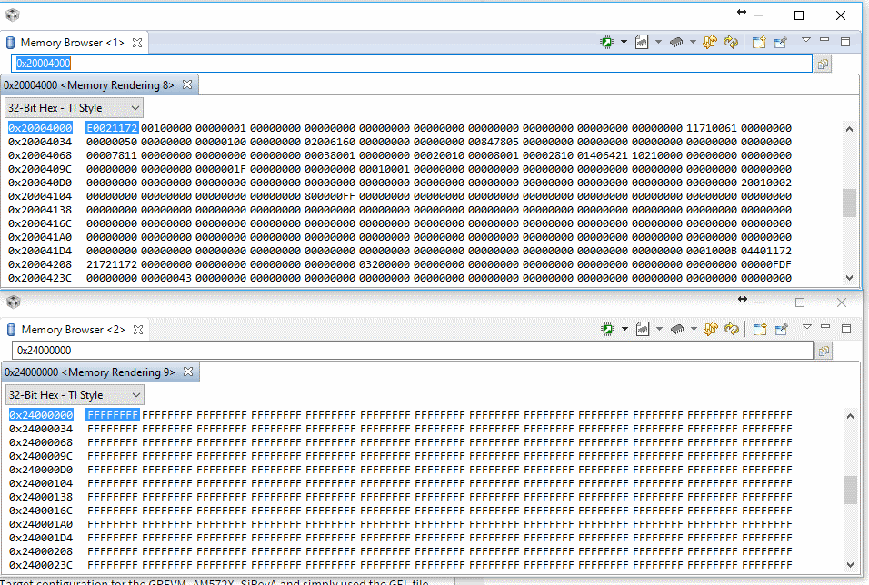
    By comparison, when I run a standalone M4, I can properly read the FPGA Vendor and device ID register at address 0x20004000. Reads to higher address return 0xFFFF which is expected since there is only 1 PCIe.

    I haven't tried data access since I need to configure the FPGA BARs from the RC (M4 in this case).

    Regards,
    - David
  • David,

    I talked to our M4 expert, from TRM Table 2-9. IPU Memory Map. The 0x2000_0000 is IPU_BITBAND region, you have to map PCIE (0x2000_0000) to L3_MAIN map: e.g. address 0x4400_0000 or 0x5600_0000 first.

    Regards, Eric
  • Hi Eric,

    Thanks for the response.
    Now the obvious question: How do you map the physical address? Do you simply do that in the custom resource table definition?

    I have tried with the resource table but it doesn't seem to help.

    Regards,
    - David
  • Hi Eric, 

    Any update on how we can map the PCIe address space to L3 main?

    Regards,

    - David

  • David,

    We do the memory mapping in resource table.

    I looked at the M4 standalone example, the outbound translation has two regions, the first region uses 0x2400_1000, so you can look remote side vendor and device ID at this address from M4. You said "I can properly read the FPGA Vendor and device ID register at address 0x20004000.", this doesn't match what I saw here. The second regions use 0x2500_0000 region for the data. I am not sure if you still use the same mapping when you run A15+IPC PCIE.

    I want to know if you accessed the right regions or not, or if this is only a mapping issue. Also, if you try adding 0x2000_0000 to the PCIE 0x2000_0000 address space in resource table (as to other regions), will it work?

    Regards, Eric
  • What you are seeing makes perfect sense. Especially after reading the TRM.

    But that is not what I am seeing in the standalone application. When I read @ 0x2400_1000 (using the memory browser of CCS), I get all FFFF with the stand-alone application.

    What GEL file are you using to initialize the M4? I created a Target configuration for the GPEVM_AM572X_SiRevA and simply used the GEL file provided. They don't seem to changed the PCIe mapping to 0x2400_0000.

    This seems like a mapping issue but I don't really know how to fix it. I find it odd that you are seeing the mapping to be @ address 2400_0000 where I see 2000_0000 for the configuration in the standalone app. I've created the example directly from the PDK using the pdkCreateExample. I pratically only changed the Board type from ipkAM572x to evmAM572x in the SYS/BIOS configuration file. 

    Regards, 

     - David

  • David,

    My test setup is IDK EVM so the Board setup in CCS target configuration is IDK_AM572x and the GEL is automatically added to intialize M4. For your GPM EVM, you can use either "GPEVM_AM572X_SiRevA" or "GPEVM_AM572X".  

    It is not the GEL that changes the PCIE from 0x2000_0000 to 0x2400_0000.

    From my stepping through the M4 code on the pcieObTransCfg() function, resSize returned is 0x0400_0000, so the regionParams.lowerBaseAddr = 0x0400_1000, that is why I knew where to look at remote side device/vendor ID.

    For your standalone M4 case,  what you get for resSize, is it 0x3000? Or how do you know you need to look at 0x2000_4000?

    Regards, Eric 

  • Hi Eric, 

    That works on the standalone application. For whatever reason when testing, I had removed the offset while creating the OB ATU region which caused issues. 

    But, that doesn't work when running on the M4 with a combined application for PCIe+IPC. I can't read memory in the 0x2400_0000 range at all. They don't seem to be mapped correctly at all. 

    I'll trace within the PCIe driver to figure what is going on...

    Quick question: Is the CSL PCIe layer used by the PCIe LLD?

    Regards,

    - David

  • Yes, PCIE LLD uses CSL PCIe layer.

    Regards, Eric
  • Hi Eric,

    I have checked when memory region 0x2400_0000 becomes available in the standalone M4 application. That region is readable as soon as the PCIe link up is detected.

    However, it never is readable in the combined application (IPC+PCIe).
    I have tried mapping 0x2000_0000 to a different memory region but that didn't change the behavior.
    FYI, I've completely remove the mapping for address 0x2000_0000 from the resource table and I'm getting exactly the same behavior. Could it be that this entry in the resource table is skipped on the M4 since address 0x2000_0000 cannot be used directly on that processor?

    Would it be worth it for me to send you my test application for you to try to replicate what I am seeing?
    You might have to disable PCIe on the linux side manually to run my application.

    Let me know.
    Right now I am stuck and will have to revert to implementing PCIe in the DSP (which is not ideal from the point-of-view of our architecture).

    Regards,
    - David
  • David,

    Do you use TI IDK or GP EVM or your own board? I am in RTOS bare metal team without much of Linux experience, if you could send me binaries of the u-boot, Linux kernel, DTB file with PCIE disabled, that would save my time to recompile it. Then for the M4 application, you may send me the file you changed with resource table, so I can adjust the table and rebuild the binary. It may take us some time to debug and get back to you. Thanks!

    Regards, Eric
  • I use GP EVM.
    Do you want the DTB for the IDK or the EVM?

    I think I only need to send you the DTB and M4 application. In the end, I have only disabled the PCIe controller from the DTB. So using the default Linux kernel and u-boot should do the trick.

    Let me know which DTB you need and I'll send all the files to you later on today.

    Regards,
    - David
  • David,

    I use AM572x IDK EVM. Please let me know the Linux RTOS release version for kernel. Also the Processor SDK RTOS release version for M4 PCIE. Do you build M4 application with CCS? Which file you added those resource mapping?

    Regards, Eric
  • Hi Eric,

    I am using Processor SDK Linux-RT version 03.01.00.06.

    I am using Processor SDK RTOS version 03.01.00.06 for the M4.

    I build my application using CCS version 6.2.0.

    I have included all the DTB that I have built. None of them should have PCIe enabled in them.

    The following file is used to define the resource table in the M4 application: rsc_table_cc_ipu.h

    The application will have to be copied on your Linux file system replacing /lib/firmware/dra7-ipu1-fw.xem4 with PCIE_RCM4.out that was built in CCS.

    Regards,

    - David

    PCIE_RCM4.zip3465.dtbs.zip

  • David,

    Thanks! The DTS disabled the PCIE as expected. I have trouble to build your PCIE_RCM4 project:

    "C:\\ti_6_1_3\\ccsv6\\utils\\bin\\gmake" -k all
    'Building file: ../Ipu1.cfg'
    'Invoking: XDCtools'
    "C:/ti/xdctools_3_32_00_06_core/xs" --xdcpath="/packages;C:/ti/bios_6_46_01_38/packages;/packages;C:/ti_6_1_3/ccsv6/ccs_base;D:/_hg/dsp/platforms;C:/ti/ipc_3_44_00_00/packages;/packages;" xdc.tools.configuro -o configPkg -t ti.targets.arm.elf.M4 -p cc.evmAM572X.M4.IPC.DRA7XX:ipu1 -r debug -b "C:/Data/E2E_Siebel/PCIE_M4/PCIE_RCM4/platform.bld" -c "C:/ti_6_1_3/ccsv6/tools/compiler/ti-cgt-arm_15.12.1.LTS" "../Ipu1.cfg"
    subdir_rules.mk:7: recipe for target 'configPkg/linker.cmd' failed
    js: "C:/ti/xdctools_3_32_00_06_core/packages/xdc/tools/Cmdr.xs", line 51: Error: xdc.tools.configuro: Error: Can't find the platform package 'cc.evmAM572X.M4.IPC.DRA7XX' along the path 'C:/packages;C:/ti/bios_6_46_01_38/packages;C:/ti_6_1_3/ccsv6/ccs_base;D:/_hg/dsp/platforms;C:/ti/ipc_3_44_00_00/packages;C:\ti\xdctools_3_32_00_06_core/packages'. Check that this path names a directory containing the necessary platform support and that the platform name is properly spelled.
    gmake: *** [configPkg/linker.cmd] Error 1
    gmake: Target 'all' not remade because of errors.

    **** Build Finished ****

    Where should I place this CCS project and code or how it find the 'cc.evmAM572X.M4.IPC.DRA7XX' ?

    Regards, Eric
  • platforms.zipHi Eric,

    I was on a business trip for the past 10 days so sorry for the delay.

    I forgot to provide you with the custom platform definition I created for the M4.

    Attached is the platform folder I am using to compile the app for the M4.

    You can simply extract that onto you computer and add that platform folder into the project platform search path.

    Let me know if you need anything more from me.

    Regards,

    - David

  • Hi Eric,

    Do you have any updates on this?
    Were you able to compile the M4 application I sent you earlier?

    Regards,
    - David
  • David,

    I was able to build your M4 application, just haven't got time to debug. Sorry for this!

    Regards, Eric
  • David,

    I apologize for the late response! I debugged the M4 PCIE issue when loaded from Linux side. My setup is two TI AM572x IDK EVMs, on side runs as PCIE EP, the other side runs as PCIE RC. I knew when M4 PCIE runs standalone the enumeration and mapping worked as the baseline.

    When RC side runs A15 Linux (with the DTB file disabled PCIE) and load the M4 image as you provided in project, I got following from M4 side:

    1) Link is up

    2) RC side OB region 1:

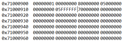
    So this region is for data access with base + 0x0500_0000 to 0x05FF_FFFF

    3) Then I modified RC side to OB region 0

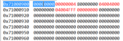
    This region is for configuration access, with base + 0x0400_4000 to 0x0404_4FFF

    With physical PCIE SS1 space unmapped (0x2000_0000 to 0x2000_0000), this is bitband region, I was not able to access 0x2400_4000 for configuration access (nothing from CCS memoey window, all ????????)

    Then, I modified:

    #define PCIE_SS1_CFG_SPACE 0x20000000

    #define PCIE_SS1_CFG_SPACE_VIRT 0xA0000000 (this is a unused region)

    and looked at below:


    0x8888104C is the remote TI PCIE device.

    For the data access, say I wrote 0xa500_0000 with a pattern:


    Then at EP side,

    I changed 0x5100_0900 =  0x8000_0000 to inbound region 0,


    Then I new I should look for 0x8005200 for data landed:

    Yes, they are there.

    So the real issue is M4 side physical to virtual address mapping. Hope this helps and give you some debug tips on your side.

    Regards, Eric

  • That's the only thing you change with my application?
    Just mapping the PCIe space to 0xA0000000 and it worked?

    Nothing else?
    Well, this is good news. I will try that very soon.

    I'll let you know how it goes.

    Regards,
    - David
  • Yes, that is the only thing I changed.

    Regards, Eric
  • Thanks Eric,

    This seems to work for me now.
    I did try re-mapping the PCIe before but I most likely used a memory region that was already reserved.

    Now, I can see the remote endpoint device and vendor ID.

    Cheers,
    - David