This thread has been locked.

If you have a related question, please click the "Ask a related question" button in the top right corner. The newly created question will be automatically linked to this question.

DM6437 : 720p video capture by CMOS Sensor

Hi,

I am trying to capture 720p video on DM6437 in YCbCr 8-bit mode, with external sync.

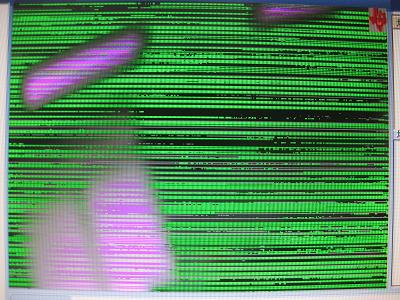
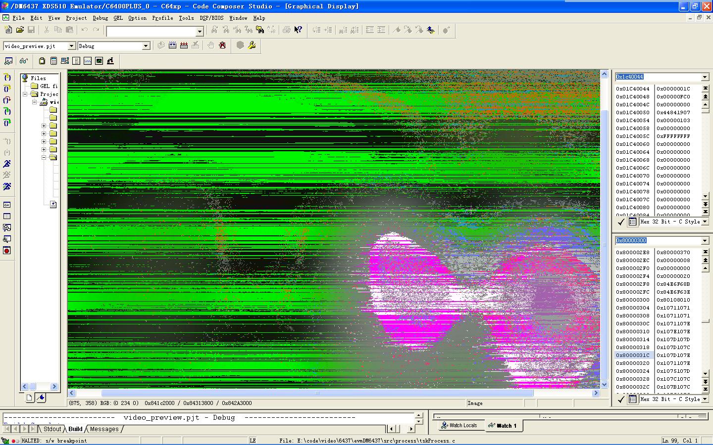
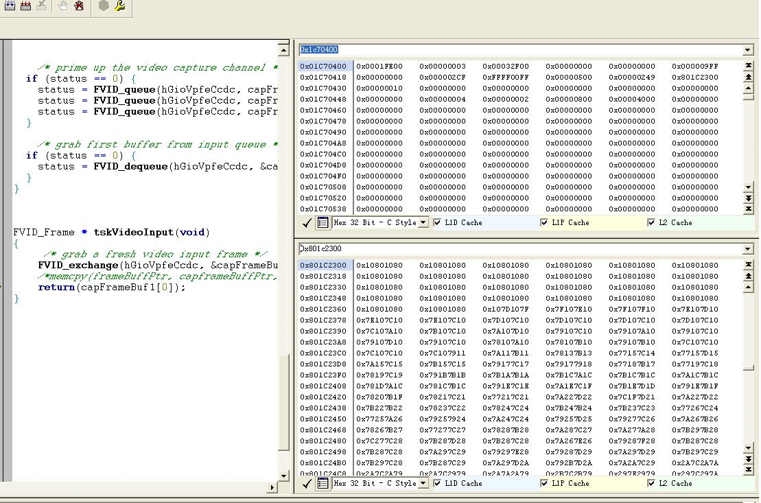
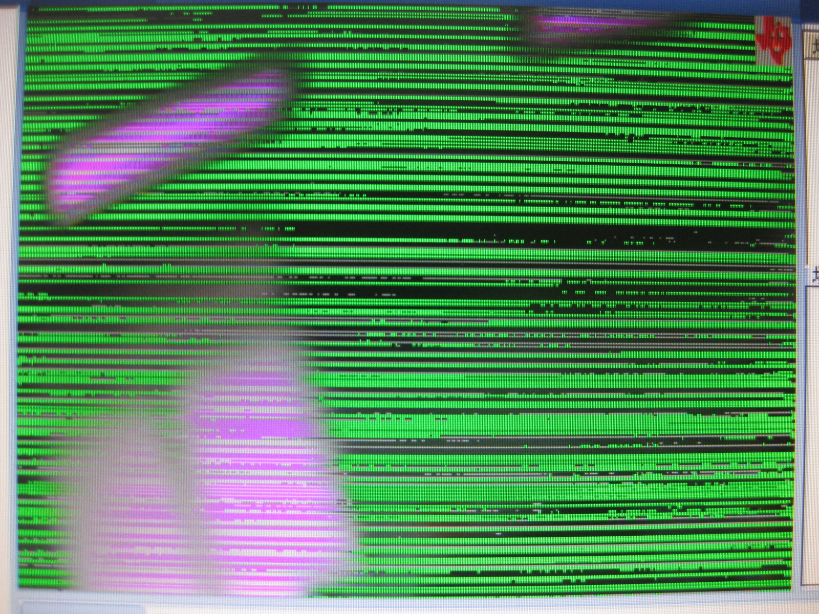
My video source(Aptina MT9D131) generates 720p video in YCbCr 8-bit format, with external sync signals (Hsync, Vsync). I have configured DM6437's VPFE in YCbCr 8-bit mode. Now I captured the image successfully when I configured the pixel-clock of sensor to 40Mhz. But failed to capture when I increase the pixel-clock to 60Mhz for more frame. Attached is the snapshot of captured video from DDR memory directly. At the same time, I connect the output of cmos sensor to DM365 board, it captured successfully by 60Mhz PCLK. I probed the PCLK and VINDATA lines, and didn't see any issue.

Refer to PCLK in spru977c.pdf, the maximum pixel clock rate of DM6437 VPFE is 71 MHZ in Normal mode. Is there any register I need to set? Is there any relationship to bandwidth of DDR or VPFE?

Regards,
Fred

  • It seems like timing related issue to me. Have you tried to change the PCLK polarity by enable PCLKINV in System modul?

  • hi,

    Can you tell me what is your VPFE CLK or DDR CLK, both should be same ?

    There is a below statement in the VPFE guide .. this means VPFE should run at > 60x2 ie 120Mhz in order to support pixel clock of 60Mhz

    "The maximum pixel clock rate is 71 MHZ in Normal mode and 90 MHZ in Turbo mode (generically,
    1 ns more than 2× the period of the VPFE clock, or CLKDIV3.)"

    DDR CLK and VPFE clock are configured to run at the same speed hence I am curious to know what the DDR speed is ?

    regards
    Kedar


  • Further can you provide the following

    - datasheet of the sensor you are using

    - YUV data file dump that is captured in memory

    - CCDC settings

  • 5618.MT9D131_DS_C[1].pdfHi,

    DDR CLk is 162Mhz x2, and is not same to PCLK. The VPFE of DM6437 is working in slave mode on our board, so the PCLK  is supplyed by CMOS Sensor(Micron Aptina MT9D131)

  • I probed the PCLK and VINDATA lines, the data is availability at the rising edge of PCLK. If the PCLK polarity is set wrong, I think the VPFE couldn't capture the image even at the PCLK is 40MHz.

  • Fred Fang said:
    I probed the PCLK and VINDATA lines, the data is availability at the rising edge of PCLK. If the PCLK polarity is set wrong, I think the VPFE couldn't capture the image even at the PCLK is 40MHz.

    At a lower pixel clock, the margin for latching the data is more.Wrong polarity can still work in slow clock. Did you already try changing the polarity? Or do you have a snapshot of the clock and VINDATA signals?

    BTW, as Kedar mentioned, if you could share your CCDC registers, we can look into the possible register configuration problems. Also, i assume you are capturing the data from the CCDC output on SDRAM. Isnt it?

    Regards,

    Anshuman

  • Thanks for your suggestion. And my colleague is trying to do. I'll relay you as soon as we having the result.

  • Hi Fred,

    Any new updates on this issue?

    Regards,

    Anshuman

  • Moved thread to the DaVinci DM64x Forum

    -Chad

  • Hi  Xiangdong,

    We have changed the polarity of PCLK by set the PCLKINV bit to '1'. Attached is the snapshot of captured video. I think it's not useful.

    Thanks you always.

  • Hi Anshuman, kedar,

    Attached is the configuration of CCDC register and the YUV data file captured in memory when the PCLK is 60Mhz.

    2055.yuv1.rar

    Regards,

    Fred

  • Hi Fred,

    Can you temporarily disconnect dm365? At least the clk & synch signals. You may be loading the line too much. Either topology or input buffer differences could be attributing to this different behavior. And let us know the result.

    Thanks,

    Cui

  • Hi Cui,

    The YUV signal is connected directly between DM365 and DM6437 on our board, so it's hard to do the test. At the same time, I've checked the input current of DM365 and DM6437, and the ouptput current of the cmos sensor, didn't see any issue.

    Refer to Maximum Data Throughput on page 79 of spru977c.pdf, the read bandwidth of CCD controller is about 10MB/s. We've calculated simply the data throughput of our 4:2:2 YUV data, is 1280 x2 x 720 x (5~6) frame when the PCLK is 40Mhz. It seems like nearly to 10MB/s. If we increase the pixel-clock to 45Mhz for more frame, the image is fail to captured at some pixel. if  to 60Mhz, the image is fully fail to captured the whole image.

    I just want to konw if the bandwidth refered above is sticking point to the problem.

  • hi Fred,

    We are unable to explain why this happens. At chip design level we have verified with 60Mhz as PCLK.

    Can you do the following,
    1. Clear the frame buffer memory will all 0xFF pattern
    2. Put a color chart in the scene
    3. Capture one frame of data, write to a file in binary format
    4. Capture same data on DM365 side, and write to file, so that we can compare original against what you are capturing on DM6437 side

    Sends us the captured frames from DM6437, DM365 side. Note we dont want screen shots, we want actual frame data memory dump

    We want to see if DM6437 video port is capturing and writing junk or not writing anything at all for some lines/pixels.

    Also can you send us the following as well,
    - Schematics for DM6437 - sensor connection
    - Oscilloscope waveforms for Hsync, Vsync, Pixel clock and data line

    Please send the above as email to Jing or me (kedarc@ti.com) in case you do not want to post this info to public forum.

    regards
    Kedar


  • We checked the PLLC1 Multiplier to x22 again and found SYSCLK1 is set to 297Mhz on our board. The VPFE can capture the 720P at about 12fps successfully when PCLK is 60Mhz after we adjust  the SYSCLK1 to 594Mhz by set the ratio of PLLDIV1(/1).

    Thanks a lot for your help.

  • Hi,

    I've faced with the similar issue and increasing of system clock (600MHz)  solved this issue. Still it's unclear  why SYSCLK1 has influence on the CCDC module. My understanding was that CCDC is clocked using PCLK(in my case 94.5MHz) and only video port interface and the rest of the modules are driven by SYSCLK1. Because I'm using raw mode and SYN_MODE.WEN is 1(Previewer, resizer, and H3A are not used) I assumed that video port interface is not used at all and the input data are latched and written directly into the DDR.

     In another words. it's not clear to me why CCDC is dependent on SYSCLK1 and where is that described?