This thread has been locked.

If you have a related question, please click the "Ask a related question" button in the top right corner. The newly created question will be automatically linked to this question.

TMS320C5517: I2S output issue of C5517

Part Number: TMS320C5517


Hi,

I have a qestion about I2S2 of C5517 device, My customer's board has problems not outputting data from I2S2.

Details are shown below:
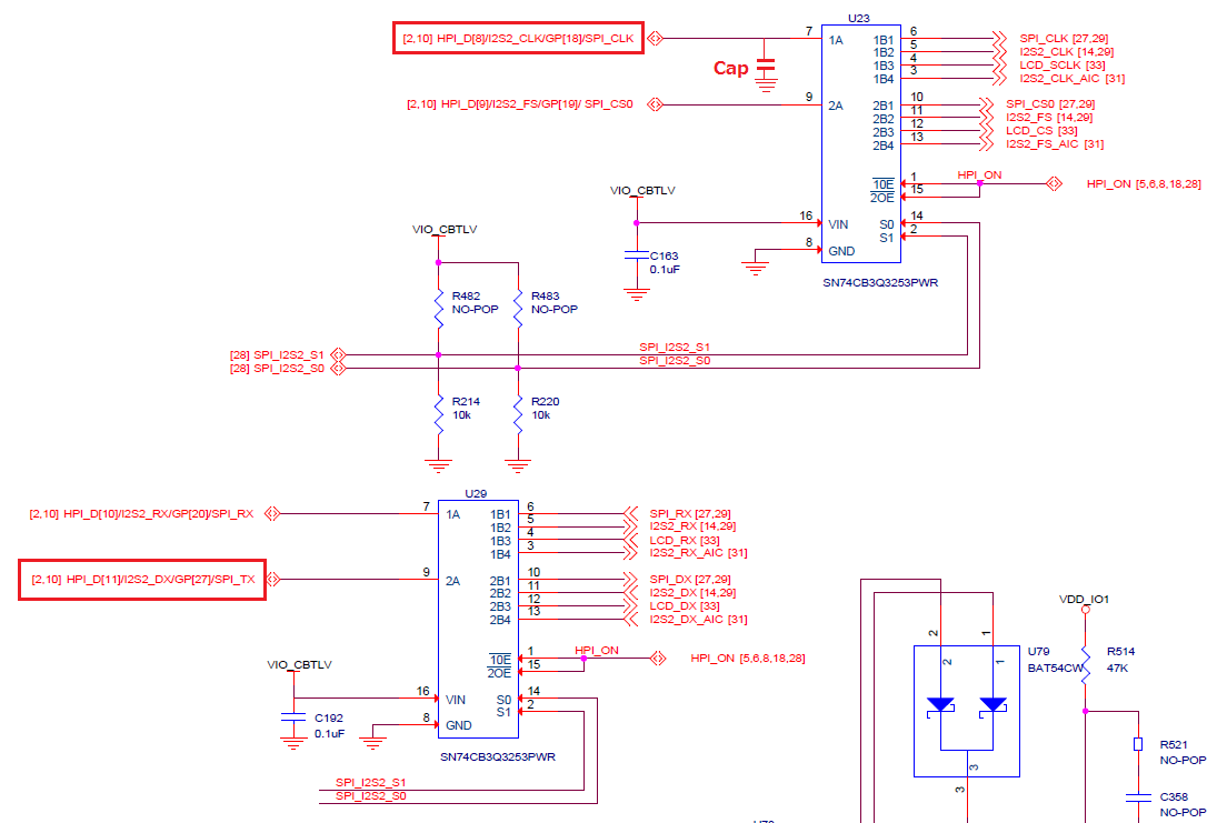
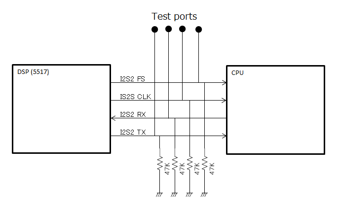
C5517 is I2S master, it connects to the slave microcomputer as shown below.

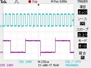
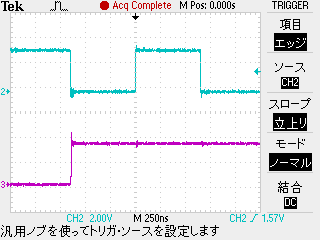
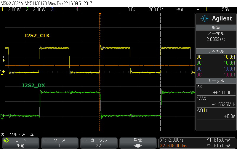
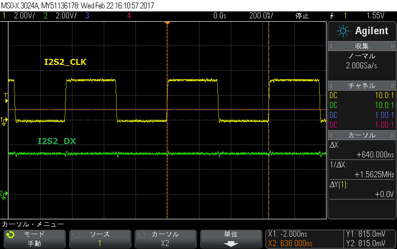
The CLK signal and the frame sync are normally output but every TX data are not output correctly, the same phenomenon occurs even if data is written directly to the TX buffer by CCS.
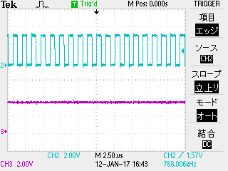
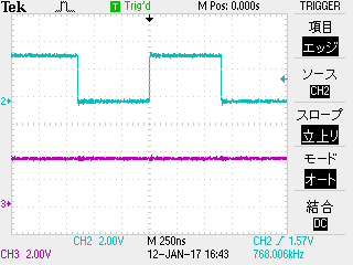
It has been confirmed that the problem is solved by the following method.

Method 1:
Cut the pattern between I2S2_CLK and Test port.

Method 2:
Change the I2S2SCTRL.DATADLY bit setting form 1 bit data delay to 2 bit. or, Use DSP format instead of I2S format.


It seems that there are some restrictions when C5517 is used as an I2S master.
Especially, Does C5517 has restrictions on the pattern length and load capacity of the I2S clock line?


Best regards,
H.U

  • Hi H.U,

    I've forwarded this to the design team. Their feedback should be posted here.

    BR
    Tsvetolin Shulev
  • Hi Tsvetolin Shulev,

    Please let me know the current status regarding this issue. I need your support.

    Best regardsm
    H.U

  • Hi H.U.,

    Unless otherwise specified, the IO timing tables are calculated with a 4pF output capacitance load - refer to 5.3.2 Electrical Characteristics in the C5517 Datasheet.

    Since the I2S timing table does not specify any other load, we must assume 4pF is the output capacitance that timing was closed with.

    The tester actually tests with a larger load of 4.0pF + 1.85pF, but this load is stated only for characterization and measurement of AC timing signals. It does not indicate the maximum load the device is capable of driving.

    I am looking into the max trace length for this signal, but it should be a function of trace impedance and resulting voltage drop, and the frequency of the signal. Reflections from the test point may also be impacting the signal integrity, but less so at slower frequencies.

    What is the frequency of your I2S CLK?

    Will it be possible to provide a scope shot of the signals at the other device (with and without the trace cut to the test point?)

    Regards,
    Mark

  • Hi Mark,

    Thank you for your reply.
    I show the waveform with the trace cut to the test point below.
    The output data was correctly.

    CH2 is I2S2_CLK, CH3 is I2S2_TX:


    The wave form below with the trace cut, and add a 30 pF capacitor to the I2S2_CLK line, measuring with the same board and the same software.
    I2S clock is clearly, but the output data was not correctly.
    It seems that if any data is written to the TX buffer, only 1 bit is output then the shift register is stopped.

    CH2 is I2S2_CLK, CH3 is I2S2_TX:
                     

    Best regards,
    H.U

  • Hi Mark,

    I’m sorry to be pressing, but any update on this issue?

    Best regards,
    H.U
  • Hi H.U.

    Sorry for the delay in this response.

    Where is the 30pF cap? Is it in series with the trace or between the trace to GND?
    I am curious if this capacitor might slightly delay the clock to the device at the other end of the I2S bus, and that device then outputs its data slightly late, which might cause a frame error on the C5517 side of the I2S bus...

    Does TX start again at next frame synch? Does it toggle out just one bit per frame or just once and then it stops forever?

    Are your I2S interrupts enabled? Do you get any interrupt like OUERR indicating a buffer over-run or under-run, or or FERR indicating too few bits received from RX line?
    You need to enable the interrupt in I2SINTMASK register and then check it in I2SINTFL register.
    I would like to the register settings of the other I2S registers if you can provide those here also (like the CLKPOL bit field of the I2SSCTRL)
    I expect to see interrupts set when you use CCS to write TX data, since you cannot possibly keep up with the I2S frame rate when writing to registers with CCS - an OUERR interrupt will fire, but I dont expect the transmit to stop entirely.

    Your software must write new data to the Transmit Left/Right Data1/0 registers as soon as the transmit interrupt occurs (with CPU polling, an interrupt service routine, or with DMA events). You should use software (and not CCS) to check the OUERR and FERR interrupts and record their occurances with software, since using CCS may make them fire.

    Refer to the following sections in the I2S section of the TRM document...
    * Emulation Considerations
    * Initialization and Configuration Steps
    * ISR Steps (for CPU transfers)

    Refer also to the CSL I2S examples that are available here: software-dl.ti.com/.../index_FDS.html

    Regards,
    Mark

  • Hello Mark-san.
    Thanks for your support always.

    Our customer has a question.

    When the I2S2 use as master,does I2S2 port receive a bad influence from surrounding environment?
    When I2S2 is used as a master, is there a limit to the capacitance capacity to be connected?

    Our customer suspecting I2S2 port.

    Could you please answer?

    Best regards,

    Manabu Ito

  • Hi Mark,

    Sorry for the late reply.


    >Where is the 30pF cap? Is it in series with the trace or between the trace to GND?

    The cap is between the trace to GND.


    >I am curious if this capacitor might slightly delay the clock to the device at the other end of the I2S bus, and that device then outputs its data slightly late, which might cause a frame error on the C5517 side of the I2S bus...

    The clock have no delay.


    >Does TX start again at next frame synch? Does it toggle out just one bit per frame or just once and then it stops forever?

    TX does not start again, It seems that the first bit continues to be output.


    I confirmed that the same phenomenon will be reproduced with EVM 5517.
    Reports the reproduction procedure.

    1.Use CSL package C: \ ti \ c5_lp \ c55_csl_3.06 \ ccs_v6.x_examples \ i2s \ CSL_I2S_PollExample

    2.By default, I2S0 instances are to be used, so change the instance to I2S2.
    Please see attached file.

    /* ============================================================================
     * Copyright (c) 2008-2012 Texas Instruments Incorporated.
     * 
     *  Redistribution and use in source and binary forms, with or without 
     *  modification, are permitted provided that the following conditions 
     *  are met:
     *
     *    Redistributions of source code must retain the above copyright 
     *    notice, this list of conditions and the following disclaimer.
     *
     *    Redistributions in binary form must reproduce the above copyright
     *    notice, this list of conditions and the following disclaimer in the 
     *    documentation and/or other materials provided with the   
     *    distribution.
     *
     *    Neither the name of Texas Instruments Incorporated nor the names of
     *    its contributors may be used to endorse or promote products derived
     *    from this software without specific prior written permission.
     *
     *  THIS SOFTWARE IS PROVIDED BY THE COPYRIGHT HOLDERS AND CONTRIBUTORS 
     *  "AS IS" AND ANY EXPRESS OR IMPLIED WARRANTIES, INCLUDING, BUT NOT 
     *  LIMITED TO, THE IMPLIED WARRANTIES OF MERCHANTABILITY AND FITNESS FOR
     *  A PARTICULAR PURPOSE ARE DISCLAIMED. IN NO EVENT SHALL THE COPYRIGHT 
     *  OWNER OR CONTRIBUTORS BE LIABLE FOR ANY DIRECT, INDIRECT, INCIDENTAL, 
     *  SPECIAL, EXEMPLARY, OR CONSEQUENTIAL DAMAGES (INCLUDING, BUT NOT 
     *  LIMITED TO, PROCUREMENT OF SUBSTITUTE GOODS OR SERVICES; LOSS OF USE,
     *  DATA, OR PROFITS; OR BUSINESS INTERRUPTION) HOWEVER CAUSED AND ON ANY
     *  THEORY OF LIABILITY, WHETHER IN CONTRACT, STRICT LIABILITY, OR TORT 
     *  (INCLUDING NEGLIGENCE OR OTHERWISE) ARISING IN ANY WAY OUT OF THE USE 
     *  OF THIS SOFTWARE, EVEN IF ADVISED OF THE POSSIBILITY OF SUCH DAMAGE.
     *
    */
    
    
    /** @file csl_i2s_PollExample.c
     *
     *  @brief Test code to verify the CSL I2S functionality in POLL mode
     *
     *
     * \page    page6  I2S EXAMPLE DOCUMENTATION
     *
     * \section I2S1   I2S EXAMPLE1 - POLL MODE TEST
     *
     * \subsection I2S1x    TEST DESCRIPTION:
     *		This test verifies the operation of CSL I2S module in polled mode.
     * I2S module on C5535/C5515/C5517 DSP is used to exchange the audio data between
     * the audio codec and DSP.
     *
     * Testing of the I2S with the audio codec is not possible as codec is not
     * part of the CSL package. This test verifies the I2S operation in loopback
     * mode. In loopback mode of operation data written to the I2S data transmit
     * registers will be transmitted to the I2S data receive registers. I2S is
     * configured to master mode, stereo, 16bit data length and to loop back mode.
     * I2S data transfer is enabled and the data is transferred to the I2S using
     * I2S_write() API. After successful completion of I2S write data is read from
     * the I2S using I2S_read() API. I2S write and read buffers are compared for
     * the data verification.
     *
     * NOTE: THIS TEST HAS BEEN DEVELOPED TO WORK WITH CHIP VERSIONS C5535, C5515
     * AND C5517. MAKE SURE THAT PROPER CHIP VERSION MACRO IS DEFINED IN THE FILE
     * c55xx_csl\inc\csl_general.h.
     *
     * \subsection I2S1y    TEST PROCEDURE:
     *  @li Open the CCS and connect the target (C5535/C5515/C5517 EVM)
     *  @li Open the project "CSL_I2S_PollExample_out.pjt" and build it
     *  @li Load the program on to the target
     *  @li Set the PLL frequency to 12.288MHz
     *  @li Run the program and observe the test result
     *  @li Repeat the test at the following PLL frequencies
     *      C5515: 60MHz and 100MHz
     *      C5517: 60MHz, 100MHz, 150MHz and 200MHz
     *      C5535 eZdsp: 60MHz and 100MHz
     *  @li Repeat the test in Release mode
     *
     * \subsection I2S1z    TEST RESULT:
     *  @li All the CSL APIs should return success
     *  @li Read and write data buffer comparison should be successful.
     *
     * ============================================================================
     */
    
    /* ============================================================================
     * Revision History
     * ================
     * 05-Sep-2008 Created
     * 10-Jul-2012 Added C5517 information
     * ============================================================================
     */
    
    #include "csl_i2s.h"
    #include <csl_general.h>
    #include <stdio.h>
    #include "csl_sysctrl.h"
    
    #define CSL_TEST_FAILED         (1)
    #define CSL_TEST_PASSED         (0)
    #define	CSL_I2S_BUF_LEN			(4)
    
    Uint16 i2sWriteBuff[CSL_I2S_BUF_LEN];
    Uint16 i2sReadBuff[CSL_I2S_BUF_LEN];
    
    /*
    	This is functionality Transmit  and
    	receive data with POLL mode.
    	The data transmission and receive happen in stereo mode.
    
    	Function returns:
    	CSL_TEST_FAILED                -Failure
    	CSL_TEST_PASSED                -Success
    */
    Int16 i2s_sample(void)
    {
    	Int16 			status = CSL_TEST_FAILED;
    	Int16 			result;
    	CSL_I2sHandle	hI2s;
    	I2S_Config		hwConfig;
    	Uint16 			looper;
    
    	/* Open the device with instance 0							*/
    	hI2s = I2S_open(I2S_INSTANCE2, I2S_POLLED, I2S_CHAN_STEREO);
    	if(NULL == hI2s)
    	{
    		status = CSL_TEST_FAILED;
    		return (status);
    	}
    	else
    	{
    		printf ("I2S Module Instance opened successfully\n");
    	}
    
        result = SYS_setEBSR(CSL_EBSR_FIELD_SP0MODE,
                             CSL_EBSR_SP0MODE_1);
        if(CSL_SOK != result)
        {
            printf("SYS_setEBSR failed\n");
            return (result);
        }
    
    	/* Set the value for the configure structure				*/
    	hwConfig.dataType 			= I2S_STEREO_ENABLE;
    	hwConfig.loopBackMode 		= I2S_LOOPBACK_ENABLE;
    	hwConfig.fsPol 				= I2S_FSPOL_LOW;
    	hwConfig.clkPol				= I2S_FALLING_EDGE;
    	hwConfig.datadelay			= I2S_DATADELAY_ONEBIT;
    	hwConfig.datapack			= I2S_DATAPACK_ENABLE;
    	hwConfig.signext			= I2S_SIGNEXT_DISABLE;
    	hwConfig.wordLen			= I2S_WORDLEN_16;
    	hwConfig.i2sMode			= I2S_MASTER;
    	hwConfig.clkDiv				= I2S_CLKDIV64;
    	hwConfig.fsDiv				= I2S_FSDIV32;
    	hwConfig.FError				= I2S_FSERROR_ENABLE;
    	hwConfig.OuError			= I2S_OUERROR_ENABLE;
    
    	/** Configure hardware registers							*/
    	result = I2S_setup(hI2s, &hwConfig);
    
    	if(result != CSL_SOK)
    	{
    		status = CSL_TEST_FAILED;
    		return (status);
    	}
    	else
    	{
    		printf ("I2S Module Configured successfully\n");
    	}
    
    
    	/* Initialize the read and write buffers					*/
    	for(looper=0; looper < CSL_I2S_BUF_LEN; looper++)
    	{
    		i2sWriteBuff[looper] = 0x001 + looper;
    		i2sReadBuff[looper]  = 0xffff;
    	}
    
    	result = I2S_transEnable(hI2s, TRUE);
    
    	for(looper=0; looper < 100; looper++);
    
    	volatile unsigned short dummy;
        while(1){
    
    //   	dummy =(* (volatile unsigned int *)(0x2810) );
    //	(* (ioport unsigned short *)(0x2809) ) = (unsigned short)(0xf0f0);		/* I2STXLT2 (upper) */
    //	(* (ioport unsigned short *)(0x2808) ) = 0xf0f0;							/* I2STXLT1 (lower) */
    
    //	(* (ioport unsigned short *)(0x280D) ) = (unsigned short)(0xffff);		/* I2STXRT2 (upper)*/
    //	(* (ioport unsigned short *)(0x280C) ) = 0xffff;
    
    	dummy =(* (volatile unsigned int *)(0x2A10) );
    	(* (ioport unsigned short *)(0x2A09) ) = (unsigned short)(0xf0f0);		/* I2STXLT2 (upper) */
    	(* (ioport unsigned short *)(0x2A08) ) = 0xf0f0;							/* I2STXLT1 (lower) */
    
    	(* (ioport unsigned short *)(0x2A0D) ) = (unsigned short)(0xffff);		/* I2STXRT2 (upper)*/
    	(* (ioport unsigned short *)(0x2A0C) ) = 0xffff;
        }
    
    
    	/* Write the buffer data to the registers					*/
    	result = I2S_write(hI2s, i2sWriteBuff, CSL_I2S_BUF_LEN);
    	if(result != CSL_SOK)
    	{
    		printf ("I2S Write Failed\n");
    		status = CSL_TEST_FAILED;
    		return (status);
    	}
    
    	/* Read data from register and buffered					*/
    	result = I2S_read(hI2s, i2sReadBuff, CSL_I2S_BUF_LEN);
    	if(result != CSL_SOK)
    	{
    		printf ("I2S Read Failed\n");
    		status = CSL_TEST_FAILED;
    		return (status);
    	}
    
    	result = I2S_transEnable(hI2s, FALSE);
    
    	/* Reset the registers										*/
    	result = I2S_reset(hI2s);
    
    	if(result != CSL_SOK)
    	{
    		status = CSL_TEST_FAILED;
    		return (status);
    	}
    	else
    	{
    		printf ("I2S Reset Successful\n");
    	}
    
    	/* Close the operation										*/
    	result = I2S_close(hI2s);
    	if(result != CSL_SOK)
    	{
    		status = CSL_TEST_FAILED;
    		return (status);
    	}
    	else
    	{
    		printf ("I2S Close Successful\n");
    	}
    
    	/* Compare the read and write buffer						*/
    	for(looper=0; looper < CSL_I2S_BUF_LEN; looper++)
    	{
    		if(i2sWriteBuff[looper] != i2sReadBuff[looper])
    		{
    			printf("I2S Read & Write Buffers doesn't Match!!!\n");
    			status = CSL_TEST_FAILED;
    			return(status);
    		}
    	}
    
    	if(looper == CSL_I2S_BUF_LEN)
    	{
    		printf("I2S Read & Write Buffers Match!!!\n");
    	}
    
    	status = CSL_TEST_PASSED;
    	return (status);
    }
    
    /*
     This is the main function to call sample program
    */
    
       /////INSTRUMENTATION FOR BATCH TESTING -- Part 1 --
       /////  Define PaSs_StAtE variable for catching errors as program executes.
       /////  Define PaSs flag for holding final pass/fail result at program completion.
            volatile Int16 PaSs_StAtE = 0x0001; // Init to 1. Reset to 0 at any monitored execution error.
            volatile Int16 PaSs = 0x0000; // Init to 0.  Updated later with PaSs_StAtE when and if
       /////                                  program flow reaches expected exit point(s).
       /////
    void main(void)
    {
    	Int16    status;
    
    	printf("CSL I2S POLLED MODE TEST!\n\n");
    
    	status = i2s_sample();
    
    	if(status != CSL_TEST_PASSED)
    	{
    		printf("\nCSL I2S POLLED MODE TEST FAILED!!\n\n");
       /////INSTRUMENTATION FOR BATCH TESTING -- Part 2 --
       /////  Reseting PaSs_StAtE to 0 if error detected here.
            PaSs_StAtE = 0x0000; // Was intialized to 1 at declaration.
       /////
    	}
    	else
    	{
    		printf("\nCSL I2S POLLED MODE TEST PASSED!!\n\n");
    	}
       /////INSTRUMENTATION FOR BATCH TESTING -- Part 3 --
       /////  At program exit, copy "PaSs_StAtE" into "PaSs".
            PaSs = PaSs_StAtE; //If flow gets here, override PaSs' initial 0 with
       /////                   // pass/fail value determined during program execution.
       /////  Note:  Program should next exit to C$$EXIT and halt, where DSS, under
       /////   control of a host PC script, will read and record the PaSs' value.
       /////
    }


    3.A capacitor of 30 pF at the U23: 7 pin on the I2S2_CLK line.

    4.Load and run the sample program prepared in Step 2 to the EVM and check the output state of I2S2_DX at U29(9 pin).

    5.When a capacitor was connected, it was observed that the output signal was not normal.
       
      The following waveform :Do not insert the capacitor :

        The following waveform :Insert the capacitor :

    Why is the data not output correctly when connect a small capacitor to the clock line?
    Could you do the same experiment?

    Best regards,
    H.U

  • Hi H.U,

    I was unable to reproduce the issue. I tried three different ways: 1) I2S2 master to CODEC slave, 2) I2S2 external loopback, 3) I2S0 master to I2S2 slave mono external loopback

    I used three different cap values to GND: 1) no caps, 2) 2 33pF caps parallel, 3) 2 parallel 33pF caps in parallel with 22uF (relatively huge)

    CVDD = 1.3V, DVDDIO = 3.3V

    Attachments: /cfs-file/__key/communityserver-discussions-components-files/791/6758.C5517-I2S-DX-stops-when-CLK-has-cap-to-GND.zip

    =-=-=-=-=-=-=-

    1) I2S2 master to CODEC slave

    project: c55_csl_3.06\c55_csl_3.06\ccs_v6.x_examples\i2s\CSL_I2S_AudioCodec_DMA

    config: C5517 I2S configured as master - AIC3204 I2S configured as slave

    Adding caps to GND to the CLK trace distorted the clock, but the I2S_TX never stopped transmitting and looked normal on the scope. In all cases, the correct data came across, passed test. Refer to scope shots...

    1) CSL_I2S_AudioCodec_DMA - no caps to GND I2S CLK rings, DX normal, 1.536MHz, pass.jpg

    2) CSL_I2S_AudioCodec_DMA - 33pf, 33pf I2S CLK lost edge overshoot, DX normal, 1.536MHz, pass.jpg

    3) CSL_I2S_AudioCodec_DMA - 33pf, 33pF, 22uF I2S CLK distorted, DX still normal, 1.536MHz, pass.jpg

    =-=-=-=-=-=-=-

    2) I2S2 external loopback

    Mr H.U. has modified c55_csl_3.06\c55_csl_3.06\ccs_v6.x_examples\i2s\CSL_I2S_PollExample

    but this example uses internal loopback mode, so I2S TX internally connects to I2S RX. The I2S signals do not leave the package and cannot be probed... If we change I2S_LOOPBACK_ENABLE to I2S_LOOPBACK_DISABLE, there is still muxing on the board that needs to be configured correctly to get the signals to the codecs and headers.

    It is easier to start with CSL_I2S_AudioCodec_DMA and merge the CSL_I2S_PollExample code into that project, calling the function after the IO Expander has been configured to set the board muxes correctly.

    hwConfig.loopBackMode = I2S_LOOPBACK_DISABLE;  // Changed from I2S_LOOPBACK_ENABLE

    hI2s = I2S_open(I2S_INSTANCE2, I2S_POLLED, I2S_CHAN_STEREO);  // Changed I2S0 to I2S2

    result = SYS_setEBSR(CSL_EBSR_FIELD_SP0MODE, CSL_EBSR_SP0MODE_1); // reset defaults EBSR PPMODE to MODE1, which muxes I2S2 out from the device...

    project: c55_csl_3.06\c55_csl_3.06\ccs_v6.x_examples\i2s\CSL_I2S_AudioCodec_DMA

    config: C5517 I2S configured as master - AIC3204 I2S configured as slave

    Adding caps to GND to the CLK trace distorted the clock, but the I2S_TX never stopped transmitting and looked normal on the scope, in all cases, the correct data came across, passed test. This test used a I2S_CLK frequency of 25MHz.

    Observation: in the case 3 with the 22uF cap to GND on the CLK, the I2S seemed to have more transactions over a longer period of time, but the data received matched the data sent... Refer to scope shots...

    Remark: Since this is an external loopback from I2S2 to I2S2, I dont think loading the I2S_CLK externally will alter the data transfer. I2S2 is the master, so it uses the internal clock to shift out and shift in the I2S data.

    1) CSL_I2S_PollExample_ExternalLB - no caps to GND I2S CLK rings, DX normal, 25MHz, pass.jpg

    2) CSL_I2S_PollExample_ExternalLB - 33pf, 33pf I2S CLK lost edge overshoot, DX normal, 25MHz, pass.jpg

    3) CSL_I2S_PollExample_ExternalLB - 33pf, 33pF, 22uF I2S CLK distorted, DX still normal but repeated, 25MHz, pass.jpg

    =-=-=-=-=-=-=-

    3) I2S0 master to I2S2 slave mono external loopback

    I thought it would be a better test if external loopback depended on the CLK signal integrity (and then experiment with the capacitive loads on the clock). For that I used the CSL_I2S0_I2S2_Mono_Example with I2S0 and I2S2 connected with jumper wires on J14 header (as described in the comments of csl_I2S0_I2S2_Mono_example.c). I then added cap load to I2S0_CLK (and attached scope probe) at J27 pin 1. I probed the I2S0_TX at J28 pin 1. Again, the I2S_CLK looked very distorted with cap load on it, but the DX pin looked normal, did not stop, and the received data matched the transmitted data.

    Refer to scope shots...

    1) CSL_I2S0_I2S2_Mono_Example - no caps to GND I2S CLK rings, DX normal, 3.125MHz, pass.jpg

    2) CSL_I2S0_I2S2_Mono_Example - 33pf, 33pf I2S CLK lost edge overshoot, DX normal, 3.125MHz, pass.jpg

    3) CSL_I2S0_I2S2_Mono_Example - 33pf, 33pF, 22uF I2S CLK distorted, DX still normal, 3.125MHz, pass.jpg

    Can you help me to reproduce the issue with the EVM and CSL code?

    Please share with me your jumper settings for J27, J28, J29, and J30

    Can you confirm the DVDDIO voltage is 3.3V when the issue is observed?

    Check also that the on-board muxing is configured to route the signals to the place where you are probing them.

    I can email you my modified version of CSL_I2S_AudioCodec_DMA with the CSL_I2S_PollExample example merged in (after IO expander configurations).

    Regards,
    Mark

  • Hi Mark,

    >Can you help me to reproduce the issue with the EVM and CSL code?

    I am requesting you a friendship. Please provide me with your test code. I would like to try it.

    >Please share with me your jumper settings for J27, J28, J29, and J30

    J27 : 1-3 = open, 2-4 = open,
    J28 : 1-3 = open, 2-4 = open,
    J29 : 1-3 = short, 2-4 = short,
    J30 : 1-3 = short, 2-4 = short,

    >Can you confirm the DVDDIO voltage is 3.3V when the issue is observed?

    DVDDIO was supplied stably at 3.3 V.

    Best regards,
    H.U