This thread has been locked.

If you have a related question, please click the "Ask a related question" button in the top right corner. The newly created question will be automatically linked to this question.

AM572X: IDK Rev. 1.3B does not boot from provided SD card

Other Parts Discussed in Thread: AM5728

hi,

     I am new to this TI processor and CCS. I am first time using this setup. i am unable to boot the board with provided SD card. I have gone through the process of creating prebuild image with TI Rtos SDK. on different SD Card but unable to get result on teraterm with baud rate of 115200 terminal dosent show any thing. 

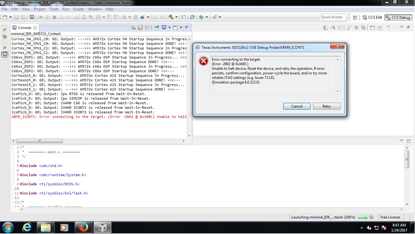
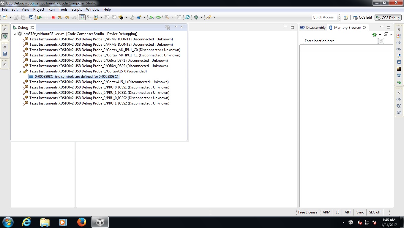
also when i run the ccs 7 and on selecting XDS100V2 USB Emulation and after clicking verify button, it display internal error occured. 

I am using 5V 2 amp power supply.

Thanks in advance,

Regards,

Nikhil

  • Hi,

    I think you need a more powerful external supply. See section 3.1 from www.ti.com/.../sprui64a.pdf for details.
  • thanks Biser for reply,
    I have checked the current drawn by board its around 1.25 A. also when i plugged sd card with "TI RTOS prebuild image" the ethernet port led starts blinking .

    as my supply current still mot reach the 2A its rating. i think there may be other issue. still i will check with increased current limit.

    Thanks & Regards,
    Nikhil
  • Please check with a larger power supply. There are very large current surges at boot time.
  • hi Biser,
    As per your suggestion i have connected 5volt 10A power supply. still no luck. on development board industrial LED2(blue) industrial LED3(glows) but no output on tera term.....
    ccs display following error when we select XDS100V2 USB Emulation and goes for verification "An internal error occurred while creating the board config text."

    thanks & Regards,
    Nikhil
  • OK, we can rule out the power supply then. What software are you trying to boot?
  • "C:\ti\processor_sdk_rtos_am57xx_3_02_00_05\prebuilt-sdcards\idkAM572x\sd_card_img" I am using.

    also i have tested with provided sd card with the kit "linux" and other "industrial sdk" same result.

    thanks & Regards,
    Nikhil
  • Thanks. I have notified the RTOs team. They will respond here. As for Linux, please note that this board is supported only by the Linux-RT SDK: software-dl.ti.com/.../index_FDS.html
  • hi,
    1) Is there any other driver for XDS100V2 USB Emulation which has to be downloaded for ccs 7 ?
    2) "C:\ti\processor_sdk_rtos_am57xx_3_02_00_05\prebuilt-sdcards\idkAM572x\sd_card_img" does it contain uboot or the provided image is bootable image with uboot?
    3) how do i check that board contains RBL ?
    4) how to get sbl prompt on teraterm ?
    5) what is the process of correctly flashing the image ?

    can you help me to understand on above points?
  • hi again,

                   my kit is "TMDXIDK5728"

                   when I select IDK_AM572x and "XDS100V2 USB"

                   It shows following screen:

    but when i select : when I select GPEVM_AM572x_sirevA and "XDS100V2 USB" following message is displayed

    with following message on box:

    """""""""""""""""""""""""""""""""""""""""""""""""

    [Start]

    Execute the command:

    %ccs_base%/common/uscif/dbgjtag -f %boarddatafile% -rv -o -F inform,logfile=yes -S pathlength -S integrity

    [Result]


    -----[Print the board config pathname(s)]------------------------------------

    C:\Users\nikhilm\AppData\Local\TEXASI~1\
    CCS\ti\0\0\BrdDat\testBoard.dat

    -----[Print the reset-command software log-file]-----------------------------

    This utility has selected a 100- or 510-class product.
    This utility will load the adapter 'jioserdesusb.dll'.
    The library build date was 'Dec 9 2016'.
    The library build time was '13:48:53'.
    The library package version is '6.0.504.1'.
    The library component version is '35.35.0.0'.
    The controller does not use a programmable FPGA.
    The controller has a version number of '4' (0x00000004).
    The controller has an insertion length of '0' (0x00000000).
    This utility will attempt to reset the controller.
    This utility has successfully reset the controller.

    -----[Print the reset-command hardware log-file]-----------------------------

    The scan-path will be reset by toggling the JTAG TRST signal.
    The controller is the FTDI FT2232 with USB interface.
    The link from controller to target is direct (without cable).
    The software is configured for FTDI FT2232 features.
    The controller cannot monitor the value on the EMU[0] pin.
    The controller cannot monitor the value on the EMU[1] pin.
    The controller cannot control the timing on output pins.
    The controller cannot control the timing on input pins.
    The scan-path link-delay has been set to exactly '0' (0x0000).

    -----[The log-file for the JTAG TCLK output generated from the PLL]----------

    There is no hardware for programming the JTAG TCLK frequency.

    -----[Measure the source and frequency of the final JTAG TCLKR input]--------

    There is no hardware for measuring the JTAG TCLK frequency.

    -----[Perform the standard path-length test on the JTAG IR and DR]-----------

    This path-length test uses blocks of 64 32-bit words.

    The test for the JTAG IR instruction path-length succeeded.
    The JTAG IR instruction path-length is 6 bits.

    The test for the JTAG DR bypass path-length succeeded.
    The JTAG DR bypass path-length is 1 bits.

    -----[Perform the Integrity scan-test on the JTAG IR]------------------------

    This test will use blocks of 64 32-bit words.
    This test will be applied just once.

    Do a test using 0xFFFFFFFF.
    Scan tests: 1, skipped: 0, failed: 0
    Do a test using 0x00000000.
    Scan tests: 2, skipped: 0, failed: 0
    Do a test using 0xFE03E0E2.
    Scan tests: 3, skipped: 0, failed: 0
    Do a test using 0x01FC1F1D.
    Scan tests: 4, skipped: 0, failed: 0
    Do a test using 0x5533CCAA.
    Scan tests: 5, skipped: 0, failed: 0
    Do a test using 0xAACC3355.
    Scan tests: 6, skipped: 0, failed: 0
    All of the values were scanned correctly.

    The JTAG IR Integrity scan-test has succeeded.

    -----[Perform the Integrity scan-test on the JTAG DR]------------------------

    This test will use blocks of 64 32-bit words.
    This test will be applied just once.

    Do a test using 0xFFFFFFFF.
    Scan tests: 1, skipped: 0, failed: 0
    Do a test using 0x00000000.
    Scan tests: 2, skipped: 0, failed: 0
    Do a test using 0xFE03E0E2.
    Scan tests: 3, skipped: 0, failed: 0
    Do a test using 0x01FC1F1D.
    Scan tests: 4, skipped: 0, failed: 0
    Do a test using 0x5533CCAA.
    Scan tests: 5, skipped: 0, failed: 0
    Do a test using 0xAACC3355.
    Scan tests: 6, skipped: 0, failed: 0
    All of the values were scanned correctly.

    The JTAG DR Integrity scan-test has succeeded.

    [End]

    """""""""""""""""""""""""""""""""""""""""""""""""""""

    I am unable to understand this;

    Regards,

    nikhil

  • Which CCS version do you have? The version recommended for AM572x devices is 6.1.3.
  • hi Biser,
    I have ccs 7.

    Thanks & Regards
    Nikhil Muley
  • hi Biser,
    I have CCS 7.

    Thanks & Regards,
    Nikhil
  • The version recommended for AM572x devices is 6.1.3.
  • hi Biser,
    As per your suggestion i have installed "CCS 6.1.3". i have insert the SD card with ti RTOS as per procedure given in "processors.wiki.ti.com/.../Processor_SDK_RTOS_Creating_a_SD_Card_with_Windows". Teraterm dosent show any message.
  • I have already notified the RTOS team. They will take this issue from here.
  • Hi,

    From your description, there are two issues need to be resolved:
    1) JTAG connection
    2) UART

    For the CCS JTAG, we have a wiki page for AM572x GP EVM at processors.wiki.ti.com/.../AM572x_GP_EVM_Hardware_Setup

    The steps for AM572x IDK EVM is similar: using XDS100V2 USB on-board connection and select" IDK_AM572X" as the device. This works with CCS 6.1.3 we recommended. We also use this in CCS/JTAG configuration, I don't see any problem. Please just create this .ccxml file before creating any CCS project. Is possible that your CCS installation is corrupted and need to re-install?

    For SD card booting, there are RTOS and Linux pre-built images. It looks that you followed the Wiki page and reflashed SD card, still no output from UART.

    You need to run some standalone UART tests to understand if this is just UART broken:
    1) there is pdk_am57xx_1_0_5\packages\ti\board\diag you can create the diagnostic applications and copy into a SD card to test UART, check processors.wiki.ti.com/.../Processor_SDK_RTOS_DIAG

    2) there are UART driver test applications (need CCS/JTAG, you need to fix this first) under processors.wiki.ti.com/.../Processor_SDK_RTOS_UART

    Regards, Eric
  • hi Eric,

    I have followed the process from wiki " processors.wiki.ti.com/.../AM572x_GP_EVM_Hardware_Setup" . 

    I am unable to understand what I am doing wrong in the process.

  • Hi,

    Can you provide the full CCS console log when you connecting to A15, here is my test for a Rev 1.3B AM572x IDK EVM for your reference:

    Cortex_M4_IPU1_C0: GEL Output: --->>> AM572x Cortex M4 Startup Sequence In Progress... <<<---

    Cortex_M4_IPU1_C0: GEL Output: --->>> AM572x Cortex M4 Startup Sequence DONE! <<<---

    Cortex_M4_IPU1_C1: GEL Output: --->>> AM572x Cortex M4 Startup Sequence In Progress... <<<---

    Cortex_M4_IPU1_C1: GEL Output: --->>> AM572x Cortex M4 Startup Sequence DONE! <<<---

    C66xx_DSP1: GEL Output: --->>> AM572x C66x DSP Startup Sequence In Progress... <<<---

    C66xx_DSP1: GEL Output: --->>> AM572x C66x DSP Startup Sequence DONE! <<<---

    C66xx_DSP2: GEL Output: --->>> AM572x C66x DSP Startup Sequence In Progress... <<<---

    C66xx_DSP2: GEL Output: --->>> AM572x C66x DSP Startup Sequence DONE! <<<---

    CortexA15_0: GEL Output: --->>> AM572x Cortex A15 Startup Sequence In Progress... <<<---

    CortexA15_0: GEL Output: --->>> AM572x Cortex A15 Startup Sequence DONE! <<<---

    CortexA15_1: GEL Output: --->>> AM572x Cortex A15 Startup Sequence In Progress... <<<---

    CortexA15_1: GEL Output: --->>> AM572x Cortex A15 Startup Sequence DONE! <<<---

    IcePick_D: GEL Output: Ipu RTOS is released from Wait-In-Reset.

    IcePick_D: GEL Output: Ipu SIMCOP is released from Wait-In-Reset.

    IcePick_D: GEL Output: IVAHD C66 is released from Wait-In-Reset.

    IcePick_D: GEL Output: IVAHD ICONT1 is released from Wait-In-Reset.

    IcePick_D: GEL Output: IVAHD ICONT2 is released from Wait-In-Reset.

    CS_DAP_DebugSS: GEL Output: --->>> CONFIGURE DEBUG DPLL settings to 1.9 GHZs  <<<---

    CS_DAP_DebugSS: GEL Output: > Setup DebugSS 1.9GHz in progress...

    CS_DAP_DebugSS: GEL Output: < Done with Setup DebugSS Trace export clock (TPIU) to 97MHz

    CS_DAP_DebugSS: GEL Output: < Done with Setup DebugSS PLL Clocking 1.9GHz

    CS_DAP_DebugSS: GEL Output: < Done with Setup DebugSS ATB Clocking 380MHz

    CS_DAP_DebugSS: GEL Output: < Done with Setup DebugSS Trace export clock (TPIU) to 97MHz

    CS_DAP_DebugSS: GEL Output: --->>> TURNING ON L3_INSTR and L3_3 clocks required for debug instrumention <<<<<<----

    CS_DAP_DebugSS: GEL Output: ---<<< L3 instrumentation clocks are enabled >>>> ---

    CS_DAP_DebugSS: GEL Output: --->>> Mapping TIMER supsend sources to default cores <<<<<<----

    CS_DAP_PC: GEL Output: Cortex-A15 1 is not in WIR mode so nothing to do.

    CortexA15_0: GEL Output: --->>> AM572x IDK EVM <<<---

    CortexA15_0: GEL Output: --->>> AM572x Target Connect Sequence Begins ... <<<---

    CortexA15_0: GEL Output: --->>> AM572x Begin MMC2 Pad Configuration <<<---

    CortexA15_0: GEL Output: --->>> AM572x End MMC2 Pad Configuration <<<---

    CortexA15_0: GEL Output: --->>> AM572x PG2.0 GP device <<<---

    CortexA15_0: GEL Output: --->>> PRCM Clock Configuration for OPPNOM in progress... <<<---

    CortexA15_0: GEL Output: Cortex A15 DPLL OPP 0 clock config is in progress...

    CortexA15_0: GEL Output: Cortex A15 DPLL is already locked, now unlocking...  

    CortexA15_0: GEL Output: Cortex A15 DPLL OPP 0 is DONE!

    CortexA15_0: GEL Output: IVA DPLL OPP 0 clock config is in progress...

    CortexA15_0: GEL Output: IVA DPLL OPP 0 is DONE!

    CortexA15_0: GEL Output: PER DPLL OPP 0 clock config in progress...

    CortexA15_0: GEL Output: PER DPLL already locked, now unlocking  

    CortexA15_0: GEL Output: PER DPLL OPP 0 is DONE!

    CortexA15_0: GEL Output: CORE DPLL OPP 0 clock config is in progress...

    CortexA15_0: GEL Output: CORE DPLL OPP  already locked, now unlocking....  

    CortexA15_0: GEL Output: CORE DPLL OPP 0 is DONE!

    CortexA15_0: GEL Output: ABE DPLL OPP 0 clock config in progress...

    CortexA15_0: GEL Output: ABE DPLL OPP 0 is DONE!

    CortexA15_0: GEL Output: GMAC DPLL OPP 0 clock config is in progress...

    CortexA15_0: GEL Output: GMAC DPLL OPP 0 is DONE!

    CortexA15_0: GEL Output: GPU DPLL OPP 0 clock config is in progress...

    CortexA15_0: GEL Output: GPU DPLL OPP 0 is DONE!

    CortexA15_0: GEL Output: DSP DPLL OPP 0 clock config is in progress...

    CortexA15_0: GEL Output: DSP DPLL OPP 0 is DONE!

    CortexA15_0: GEL Output: PCIE_REF DPLL OPP 0 clock config is in progress...

    CortexA15_0: GEL Output: PCIE_REF DPLL OPP 0 is DONE!

    CortexA15_0: GEL Output: --->>> PRCM Clock Configuration for OPP 0 is DONE! <<<---

    CortexA15_0: GEL Output: --->>> PRCM Configuration for all modules in progress... <<<---

    CortexA15_0: GEL Output: --->>> PRCM Configuration for all modules is DONE! <<<---

    CortexA15_0: GEL Output: --->>> DDR3 Initialization is in progress ... <<<---

    CortexA15_0: GEL Output: DDR DPLL clock config for 532MHz is in progress...

    CortexA15_0: GEL Output: DDR DPLL clock config for 532MHz is in DONE!

    CortexA15_0: GEL Output:        Launch full leveling

    CortexA15_0: GEL Output:        Updating slave ratios in PHY_STATUSx registers

    CortexA15_0: GEL Output:        as per HW leveling output

    CortexA15_0: GEL Output:        HW leveling is now disabled. Using slave ratios from

    CortexA15_0: GEL Output:        PHY_STATUSx registers

    CortexA15_0: GEL Output:        Two EMIFs in interleaved mode - (2GB total)

    CortexA15_0: GEL Output: --->>> DDR3 Initialization is DONE! <<<---

    CortexA15_0: GEL Output: --->>> AM572x Target Connect Sequence DONE !!!!!  <<<---

    CortexA15_0: GEL Output: --->>> IPU1SS Initialization is in progress ... <<<---

    CortexA15_0: GEL Output: --->>> IPU1SS Initialization is DONE! <<<---

    CortexA15_0: GEL Output: --->>> IPU2SS Initialization is in progress ... <<<---

    CortexA15_0: GEL Output: --->>> IPU2SS Initialization is DONE! <<<---

    CortexA15_0: GEL Output: --->>> DSP1SS Initialization is in progress ... <<<---

    CortexA15_0: GEL Output: DEBUG: Clock is active ...

    CortexA15_0: GEL Output: DEBUG: Checking for data integrity in DSPSS L2RAM ...

    CortexA15_0: GEL Output: DEBUG: Data integrity check in GEM L2RAM is sucessful!

    CortexA15_0: GEL Output: --->>> DSP1SS Initialization is DONE! <<<---

    CortexA15_0: GEL Output: >> START ==> Enable L3 Clk

    CortexA15_0: GEL Output: >> Change Suspend source for GPTimer5 to DSP1

    CortexA15_0: GEL Output: --->>> DSP2SS Initialization is in progress ... <<<---

    CortexA15_0: GEL Output: DEBUG: Clock is active ...

    CortexA15_0: GEL Output: DEBUG: Checking for data integrity in DSPSS L2RAM ...

    CortexA15_0: GEL Output: DEBUG: Data integrity check in GEM L2RAM is sucessful!

    CortexA15_0: GEL Output: --->>> DSP2SS Initialization is DONE! <<<---

    CortexA15_0: GEL Output: --->>> IVAHD Initialization is in progress ... <<<---

    CortexA15_0: GEL Output: DEBUG: Clock is active ...

    CortexA15_0: GEL Output: --->>> IVAHD Initialization is DONE! ... <<<---

    CortexA15_0: GEL Output: --->>> PRUSS 1 and 2 Initialization is in progress ... <<<---

    CortexA15_0: GEL Output: --->>> PRUSS 1 and 2 Initialization is in complete ... <<<---

    https://e2e.ti.com/cfs-file/__key/communityserver-discussions-components-files/791/AM572_5F00_IDK_5F00_100v2.ccxmlAlso attached my CCS target configuration file for reference, note my CCS installed under c:\ti_6_1_3 instead of c:\ti.

    Regards, Eric

  • hi Eric,

                 Thanks for providing your ccs target configuration file, on your target configuration file I have changed path from "c:\ti_6_1_3" to "c:\ti" and then make this file as active and then build the project.

    I have got following result.

    After Clicking on connect to Target Button.
    Following Screen Display

    I have also attached my demo project file ... please take a look at it let me know what went wrong.

    workspace_v6_1_3.rar

    Thanks & Regards,

    Nikhil Muley

  • hi Eric,
    I got my mistake that i was doing ...... while connecting target I was connecting to arm 9 ...... when i select cortex A15_0 core ........ i got the result that you have posted above .....
    but Still my RTOS Sd card doesn't boot
    can you provide me the Steps for creating the RTOS diagnostic application on windows

    Thanks & Regards,
    Nikhil Muley

  • Hi,

    Good to know you can connect to EVM now from JTAG! The way to create RTOS Diag, please check processors.wiki.ti.com/.../Processor_SDK_RTOS_DIAG

    In short:
    1) Run pdksetupenv to configure your build env
    2) run "gmake idkAM572x_sd" to build
    3) copy files into SD card
    4) insert SD card into EVM and power on, you should see printout on UART

    If you doesn't see anything, please connect CCS/JTAG with all the GEL files REMOVED to A15 core to see where the program counter is.

    Regards, Eric
  • Hi Eric,
    I have followed the step suggested by you and successfully created the SD card, there was no print out on Teraterm with 115200 baudrate.
    also can you guide me on removing the GEL Files as you said in "If you doesn't see anything, please connect CCS/JTAG with all the GEL files REMOVED to A15 core to see where the program counter is."
    This question might look silly, but I am New to ccs environment. tell me how can I achieve connecting debugger with all GEL files removed?

    Thanks & Regards,
    Nikhil Muley
  • Hi,

    Keep you original CCXML file which has GELs associated to connect to the EVM. Please create a new ccxml use the same xds200 JTAG, but in device select "AM5728", not those IDK or GPEVM, so this ccxml will not have any GELs.

    When you copied the diagnostic files and boot from SD card, as you see nothing from UART, please use this new ccxml to connect to the A15 core (there is no GEL to intialize the SOC again, this already done by MLO). If you see the A15 PC is at 0x3_xxxx address, it means the boot didn't work. If you see PC is at 0x4xxx_xxxx, that is boot happens, may be the UART breaks?

    Another way is to use the UART test examples with your original ccxml to initialize the SOC, and to see if you see anything on UART.

    Regards, Eric
  • Hi Eric,

          Thanks for explanation. i have created a new ccxml with device selection as "AM5728" and after  that connection was tested which was ok. But when I try to connect to A15_0 core i got following error:

    How to remove the above error ?

    Thanks & Regards,

    Nikhil Muley

  • hi Eric,

                when i try to connect the A15_0 without GEL and without TI RTOS SD Card.

    Program counter is on following location:

    Thanks & Regards,

    Nikhil Muley

  • Hi,

    when i try to connect the A15_0 without GEL and without TI RTOS SD Card, PC at 0x3_xxxx looks right.

    As we are debugging why there is nothing on UART, can you "i try to connect the A15_0 without GEL and WITH TI RTOS SD Card", where is the PC?

    Regards, Eric

  • Hi Eric,

                 you pointed out" As we are debugging why there is nothing on UART" exactly the same problem that i am facing right now. when i try to connect the A15_0 without GEL and with TI RTOS SD Card loaded, i got following error when i try to connect to core A15_0 and there is no data on PC.

    Thanks & Regards,

    Nikhil Muley

  • hi Eric,
    As i have lost much of time on starting the board, i haven't started coding on real application, i request you, Is it possible for you to come online at your convenience time, so that problem can be solved quickly. I can also arrange the access to "teamviewer" with am572x IDK.

    Thanks & Regards,
    Nikhil Muley
  • Hi,

    Sorry, I can't do on-line support. Do you have a local FAE to work with? As JTAG is working, UART nothing printed. Either you use the our diagnostic code (create the SD card) to see if anything printed on UART, or we have standalone UART test project, you can build and use JTAG/CCS to run, to see if UART working.

    Regards, Eric
  • Hi Eric,

               Thanks for reply, I have tried with diagnostic code (create the SD card) and no success with uart, also JTAG/CCS doesn't enter the processor when  diagnostic sd card is loaded. can you provide the example of 

    standalone UART test project (with all files) so that we will be on same platform and this could help in better understanding whats going on with board (AM572x IDK).

    Thanks & Regards,

    Nikhil Muley

  • Hi,

    Please check then PDK Example and "Test Project Creation" to create your UART CCS project. Then load into CCS, build and run, to see if you see anything from UART.

    For your reference, I just did the same and attached the .out file here https://e2e.ti.com/cfs-file/__key/communityserver-discussions-components-files/791/UART_5F00_BasicExample_5F00_idkAM572x_5F00_armExampleProject.out, you can directly load and run on A15 core. You should see something in UART.

    Regards, Eric

  • Hi Eric, 

                 I have attached the steps carried out, along with console. please go through it. I have directly loaded your .out file but got error. It is showing error on executing Board_Init(board_cfg); step. Nothing on Uart

    test_out.rar

    can you provide more insight on whats going during board init. and what causing uart not functional also I have run the basic hello world example on A15_core successfully console shows the result.

    Thanks & Regards,

    Nikhil Muley

  • Hi,

    I compared my CCS console output to yours, it is exact the same except the JTAG/DAP failure at the end, which happened when you run the program. The screenshots also look OK. I then loaded the out file from the *.zip (is that your own or mine?), it worked to print info on UART without any issue.

    There are many driver examples in PDK 1.0.5, did you try any others in addition to this UART one? Did they crash as well? All the examples have such routine Board_init() at the beginning, although may have the different flag passing into it. If UART example crashed, I expect that other driver examples will crash as well. The simply one "hello world" just print something to CCS console without PINMUX|UART setting passed into the board_init().

    I don't know what was wrong to the EVM you have. If you have to debug, you can try different combinations of:

    boardCfg = BOARD_INIT_PINMUX_CONFIG |
    BOARD_INIT_UART_STDIO;

    To see which flag caused the DAP/JTAG failure. Then step into the code for that flag to see which portion failed \ti\board\src\idkAM572x\idkAM572x.c:

    if (cfg & BOARD_INIT_PINMUX_CONFIG)
    ret = Board_pinmuxConfig();

    if (cfg & BOARD_INIT_UART_STDIO)
    ret = Board_uartStdioInit();

    Do you have another board to try or this is the only one?

    Regards, Eric
  • Hi Eric,

                  " I then loaded the out file from the *.zip (is that your own or mine?)"

    you are absolutely right it was yours .out file which i have loaded in to Am572x IDK board

    ."did you try any others in addition to this UART one?"

    No. But i will try and let you know the result.

    any more points to be taken care while trying the example?

    Thanks & Regards,

    Nikhil Muley

  • hi Eric,
    When I load the .out file provided by you " UART_BasicExample_idkAM572x_armExampleProject.out " .I got error at Board_init(boardCfg); "Can't find a source file at "src/idkAM572x/idkAM572x.c" . i have checked that location " idkAM572x.c " file was present.

    Thanks & Regards,
    Nikhil Muley
  • Hi Eric,
    Thanks for time and support. finally i have applied for replacement of board.

    Thanks & Regards,
    Nikhil Muley