This thread has been locked.

If you have a related question, please click the "Ask a related question" button in the top right corner. The newly created question will be automatically linked to this question.

TMS320C5517: EMIF EMIF Asynchronous Memory timing requirements

Part Number: TMS320C5517

Hi,

I have qestion about EMIF timing of C5517.
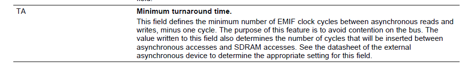
The td(TURNAROUND) is described as follows.

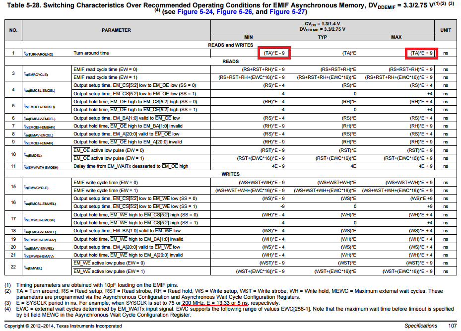
If SYSCLK is used at 200 Mhz, the minimum value will be a negative value, so I think that this prescribed value is wrong.
Is the margin (± 9 ns) incorrect?

Best regards,
H.U

  • Hi,

    I've notified the design team to elaborate. Their feedback will be posted here.

    Best Regards,
    Yordan
  • Hi Yordan,

    Any update on this issue?
    I need your help.

    Best regards,
    H.U

  • Hi H.U.,

    I understand your concern about a negative Turnaround time that is possible when the TA parameter is set to 0.

    The TA bits can be programmed with 0, 1, 2, or 3. Under use case CVDD = 1.3/1.4 V / DVDDEMIF = 3.3/2.75 V, the margin of +/- 9ns can result in a negative turnaround time. (according to the C5517 datasheet, under all CVDD/DVDDEMIF voltage cases when the TA bits are set to 0, the minimum turnaround time is negative...)

    I am tracking down the timing closure source of these margins, which are higher for all other CVDD/DVDDEMIF voltages on C5517.
    One interesting point is that under all cases, the predecessor (C5515) EMIF timings always result in a positive min turnaround time - due to slower clock speeds and tighter margins (+/- 7.5ns)...

    C5517 1.4-V Core (200 MHz)
    CVDD = 1.3/1.4 V / DVDDEMIF = 3.3/2.75 V
    E = 5, Plus/Minus = 9
    TA = 3+1:      Min = 11.00        Nom = 20.00        Max = 29.00
    TA = 2+1:     Min = 6.00        Nom = 15.00        Max = 24.00
    TA = 1+1:     Min = 1.00        Nom = 10.00     Max = 19.00
    TA = 0+1:     Min = -4.00        Nom = 5.00        Max = 14.00

    One way of avoiding this negative minimum is to program into TA something greater than 0 (note that the reset value is 3).

    I will get back to you when I find out more details.

    Hope this helps,
    Mark

  • Hi Mark,

    Thank you for your reply, yes your understanding is correct!
    I want to know that why the minimum value can set negative value and how does it behave when the minimum value is set to a negative value by using TA register field is set to 0?

    Best regards,
    H.U

  • Hi Mark,

    Any update on this issue? I need your help.

    Best regards,
    H.U
  • Hi Mark,

    I’m waiting for your reply.
    Your immediate response is highly appreciated.

    Best regards,
    H.U
  • Hi H.U,

    The turnaround time is what is specified in the datasheet timing tables.
    The min and max turnaround times depend on core voltage, IO voltage, and SYSCLK frequency.
    If the turnaround time is negative when TA=0, then the customer must either set TA > 0 or slow the system clock down until the min turn around time is greater than 0. They should also consider if a turnaround time of 0ns or 1ns is sufficient for their system. Maybe they need to use TA = 2 or 3 to ensure there is enough guaranteed minimum turnaround time.

    Why the minimum value can set negative value?
    These are the numbers that were calculated during the timing closure phase of the design of the C5517 device.

    How does it behave when the minimum value is set to a negative value by using TA register field is set to 0?
    Potentially some devices (on the outside of the process bell curve) could experience contention on the bus when asynch read is followed by asynch write or visa versa. There may also not be enough time between asynchronous accesses and SDRAM accesses, if applicable. I have not proved this with hardware.

    Hope this helps,
    Mark

  • Hi Mark-san,

    OK, I understand that. Thank you for answer.

    Best regards,
    H.U