This thread has been locked.

If you have a related question, please click the "Ask a related question" button in the top right corner. The newly created question will be automatically linked to this question.

5510 HPI - Is it required that the 5510 boot in EHPI boot mode for the HPI to work?

Other Parts Discussed in Thread: TMS320VC5510A

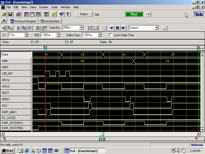
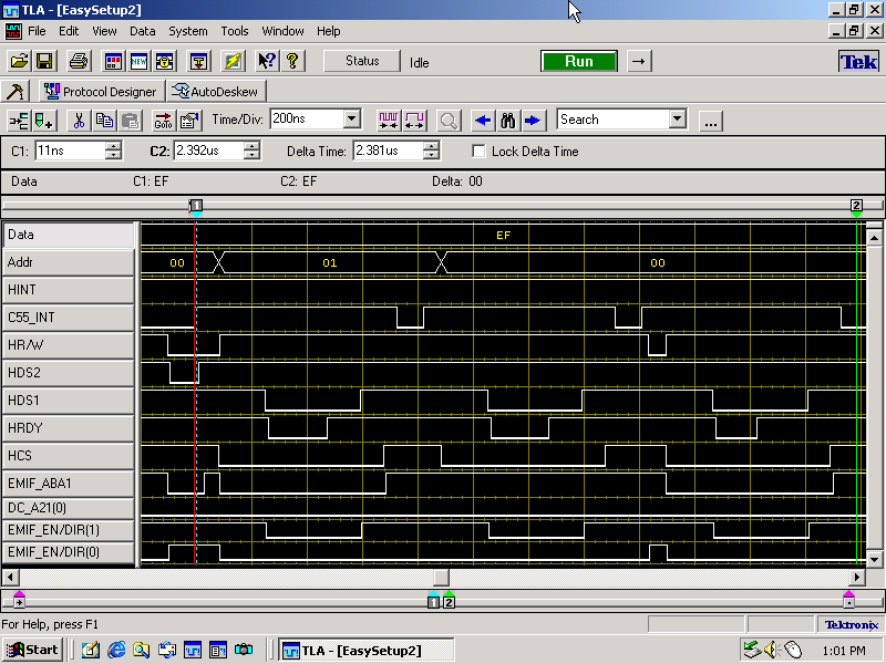
I know that on the 5510, the DMA controller is responsible for getting the data from the HPID (data register) to memory.  My problem with this is that it's a dedicated DMA channel, and while I can configure any of the other 6 DMA channels, it seems that configuration of the HPI DMA channel is automatic.  Among other reasons I have for believing this is the fact that the HPI can be used to bootload program code into the 5510, indicating that nothing need be configured prior to using the interface.  Is this assumption correct, or can someone point me towards a resource which would indicate proper configuration of the HPI DMA channel on the 5510?  Again, I feel it should be as simple as ensuring the control signals are properly timed as well as having data and address pins strobed at the proper times - all things taken care of by the EMIFA interface.  On the 5510, I can access (write/read) the HPIC control register, but have still not managed to get data through to a specific memory location.  I am using the non-multiplexed mode for the 5510 HPI.

I've read the following documents numerous times: spru588b TMS320VC5510 DSP/HPI Reference Guide, spra741 Using the TMS320VC5510 Enhanced HPI, spra763c Using the 5510 Bootloader, sprs0760 TMS320VC5510 DSP (datasheet)

Is it possible that to use HPI, the 5510 processor be started up in EHPI boot mode?

  • Derek,

    I believe that you have identified most of the relevant documentation for the HPI on the C5510 DSP.  The only other document I see is an app note: spraa24 HPI Througput and Optimization.

    It is not necessary to boot through HPI to later use it with your application code.  As you note, all configuration / management of the HPI/DMA is done through signaling from the host.  There is nothing to do from the DSP.  The only function the DSP can manage regarding the HPI is to generated an interrupt request signal to the host.

    Regards.

  • Thank you, Tommy, for your reply.  Yes, I have also looked over the spraa24 application note; however, at this time I'm not as worried about maximizing my HPI throughput as simply getting a few data points through.  It would seem that I am able to write the HPI control register, HPIC, but I can't get any data through.  I know I am able to write the control register because I can write to the DSPINT bit, and the 5510 will break off into the ISR I have configured for this interrupt.  However, according to p. 17 of spra741 ( http://dspvillage.ti.com/pdfs/spra741.pdf ), writing a 0 to the RESET bit of HPIC will cause the DSP to be put in reset until the host sets the RESET bit to 1.  I have not seen this behavior, but I've thought that could be because I'm not starting up in HPI boot mode.

    I have not verified proper reading from the HPIC register, and I have some suspicions about whether I am properly reading it.  My reasoning is that if I write to the XADD bit, I should be able to read this back, but this may be an incorrect assumption as I am operating in non-multiplexed mode (I have not been able to successfully read the XADD bit).  As the DSPINT and RESET bits always read 0, and if I don't have the EHPI bus holders enabled in the SYSR system register, I always read 0 from HPIC.  Of course if I have the bus holders enabled, I read what was last written (whether it be HPID or HPIC).

    Any ideas as to why HPIC writes seem to work while HPID writes do not?  I have considered that maybe I'm improperly addressing the HPI bus, but I've tried writing to large portions of the addressable regions, then performed a 5510 memory dump, and not seen my test writes anywhere.  Your help is appreciated.


  • Tommy, I read more closely over that application note, and it turns out to be the exact guide which explains why I'm experiencing the problems I'm seeing.  I'm now figuring out how to make the transactions work, and hopefully this new understanding will alleviate my headache.  Essentially the HRDY signal from the 5510 is completely different than the ARDY signal in the 6455 (and subsequently different from what I understood it to be).  If I have any more questions, I'll post again later.  Thanks for your help!

  •  

    One more quick question: If my 5510 breaks off into the ISR set up for the DSPINT bit in the HPIC control register (i.e. HWI 10), can I conclude that HPIC writing is functioning properly?  I've been proceeding with the simple answer of "yes" but maybe I'm wrong.

    I cannot envision any scenario which would cause HPIC writes to function properly but not allow reading of this register, in addition to not allowing writing/reading of HPID, but perhaps someone else can think of one?


    Okay, below I have HPID write/read logical analyzer screengrabs.  Note that only the 8 LSBs of the data and address buses are probed.  For the write, I write to 3 consecutive addresses the values 0xFACE, 0xDEAD, 0xBEEF.  For the read, I try to read these 3 consecutive addresses.  Note that during the read, the only values on the data bus are that which were written last - i.e. 0xEF (this happens when I've enabled the EHPI data bus holders; otherwise, I would read 0xFF if my logic analyzer probes are connected to the bus or 0x0 if not).  All control signals look good, and the HRDY signal is strobing as if the data is being properly extracted from the buses to memory.  Anyone see anything that might not look right in these signals?

    Write:

    Read:

  • Hi Derek,

    Are you meeting the 4ns setup and 4ns hold time specs E13, E14?  It is hard to tell at 200ns/period.

    I agree that the HRDY response looks reasonable on writes.    For Reads, based on my C6x experience,  I might have expected the 2nd and 3rd Read HRDY to be much shorter/faster/sooner due to fetch ahead, if HPID++ mode were correctly accessed.

    What is C55_INT signal?    What are EMIF_ABA1, and EMIF_EN/DIR[1:0] signals connected to on the HPI side? 

      --Joel Graber  


  • Thanks for your response.  Yes, I'm meeting the E13/E14 timing specs by a significant margin.

    My current application is this: I'm using a C6455 EMIF to communicate with the C5510's HPI.  The chips reside on a DSK6455 and DSK5510, respectively, with a daughter card connecting the two boards.

    I'm using the C5510 HPI in non-multiplexed, non-autoincrement mode, so I'm not sure HPID++ mode applies?  I'm currently trying to do memory accesses one halfword at a time (a simple *pHPI = data or data = *pHPI) and consequently not using DMA from my master DSP.  So I'm not sure if fetch ahead applies.  But perhaps you're onto something with my inability to access the 5510 memory - could you elucidate your point?

    The C55_INT signal is from my C6455 and is used 1.) as a trigger for my scope and logic analyzer and 2.) as a secondary means of generating an interrupt to the 5510.  Currently the 5510 ISR is set to simply toggle an LED on the DSK5510 board.  The EMIF_ABA1, EMIF_EN/DIR[1:0] lines are not connected to anything on the 5510 and are signals off my DSK6455 board.  The EMIF_ABA1 represents the LSB of the 16-bit address and will eventually be connected to HA0 on the 5510, and the EMIF_EN/DIR signals are from the CPLD on the board which go to a pair of bus transceivers which drive the C6455 EMIF signals to the DSK6455 external memory interface connector.

  • OK,    HPID++ does not apply for you.    I'm reading from spra741a.pdf.

    Your non-multiplexed mode means HMODE is driven high, and you are providing HAddr on its own bus (Addr in the waveforms).

    HCNTL[0]   needs to be 0 for HPIC access and 1 for HPID access, is it shown in your waveform?

    You mention doing half-word accesses, but the C55 is a 16 bit machine, so all accesses are half-word=16bits anyway.  So you shouldnt have to worry about the high-half-lowhalf ordering of a 32bit word here if you are only accessing 16bit memory internal to the C55,  which is a good place to start.

    What address are you using in the C55 global memory map?  Section 3.2.3 and figure 3.4 of tms320vc5510a.pdf shows that address 0 is not accessible to EHPI.  If addressing CE0 space, then the EMIF registers for that space need to be setup first.

    --Joel Graber


  • On the DSK5510, HMODE is held high through external logic, and I have verified that with a scope.  I am providing HA on its own bus, as you noted.  In the logic analyzer screengrabs, I have only shown the 8 LSBs of the address and data buses.

    HCNTL[0] is low for HPIC access, but for these grabs, it was 1 since I was trying to do data access.  I have this wired to a switch on my board and have verified its level.  And yes, regarding endian-ness, I do not have to worry about this, as the C5510 uses 16-bit bytes.

    In the C5510 memory, I am trying to access word address 0x18000 (byte address 0x30000) in the middle of SARAM.  From my C6455, I am using CE4 space for EMIF, and I am fairly certain all of my configuration for C6455 EMIF has been done correctly.

    As far as HPI goes, I have only been able to write to HPIC (though not read from it), and I have not successfully read or written HPID.  I'm stumped because it would appear that all the various control signals seem correct (I have even verified their integrity with a scope - no ringing or overshoot, good levels).  Thanks again for your continued help!

  • Summary:  The HRDY activity suggests that the proper internal activity is happening, but you have no other evidence of that, such as any output from HData bus.    

    Here are some additional debug brainstorms to try,  no particular order, numbered only for future reference.

    1. Some problem with driving the HD bus as output?:   Use CCS to write to CPU side of HPIC to set and release HINT, to show that it can be toggled.  This should be sufficient test that TRST and EMU1 are not set to "OFF" mode functionality.   Is there any other reason why all pins, or Hdata pins would have their outputs disabled?

    2  Is the internal activity really happening?    Try write with HPI to SARAM, and then use CCS monitor to show internal contents of that address to see if it changed.   Also try the reverse,  use CCS to write a large range of nearby addresses with data=address.  Then use HPI read to see if you get any change on HData bus.

    3. Try with/without HPE internal pullup/pulldown enable/disable bit in the SYSR?

    4. Can HData write and read to HPIA?  Change into muxed-mode and do write and readback operations on HPIA register.  No memory accesses are involved, HRDY typically does not toggle.

    --joel

  • The HRDY activity indicates to me that the processor is doing something with the data, but you are correct in that I have no other evidence of that.  The only evidence I have that anything over HPI is working is the following:

    If I write 0x3 (DSPINT = 1 and RESET = 1) to HPIC from my host processor, I see the corresponding bit in the C5510 IFR (i.e. Interrupt 10) change.  I can hook an ISR to this interrupt, and the ISR triggers as it should.  This leads me to believe that HPIC writes are working.  Since the DSPINT bit and the RESET bit always read 0, I have tried writing to the XADD bit, then reading it back but to no avail.

    Some of your questions I can answer, and I will work further on your suggestions.

    1.) I believe HINT is an HPI signal and is not triggered through the HPIC, but rather through the ST3 status register.  I am able to toggle this signal line by setting/clearing the corresponding bit in ST3.  I have verified this with a scope - additionally I have set it to successfully trigger an ISR in the host processor.  But you indicate the ability to write HPIC through CCS, and knowing how to do so would be extremely helpful!  I thought that HPIC/HPID/HPIA were not memory-mapped registers, so one was not able to view or set them from the DSP (or for that matter from CCS).  I can think of no reason why the HD pins would have their outputs disabled, as I've not disabled them, at least not explicitly, and my C5510 application is VERY simplistic (I don't think I would know how to disable them either).  Is there a way through software or CCS to ensure that they are not disabled?  I'm also not familiar with TRST and EMU1, so is there a way to ensure that they're "ON", should they need to be?

    2.) I've tried writing to SARAM with HPI and viewing the C5510 memory contents through CCS.  The contents don't change at all.  I thought perhaps it was an addressing issue, so let's say I write to ADDR.  If it's an issue such as halfword addressing vs word addressing vs perhaps byte addressing, I should be able to see my written contents at ADDR or ADDR<<1 or ADDR<<2 or ADDR>>1 or ADDR>>2, but I don't.  There's no indication that the data I write gets into memory.  Additionally, I've tried setting the contents of my memory segment to some known pattern by using a 'for' loop in the C5510 application, then attempted to read back this data from my host.  All I see is 0xFF or 0x0 (depending on whether my logic analyzer probes are plugged in or not, respectively).  I never see the data bus actually change either.  As you suggested, I will try filling memory through the CCS debugger then try to read it back to see if I see a change on the HD bus.

    3.) I've tried enabling the HPE bit in SYSR. If I enable HPE and I write to the data bus (either an HPIC or HPID access), I will always read back exactly what I just wrote.  For example, I write 0x3 to HPIC (i.e. HCNTL[0] low) then write 0x1234 to HPID (i.e. HCNTL[0] high). If I do a read, I will always read back 0x1234 regardless of HCNTL[0].  Alternatively, if I write HPID 0x1234 then HPIC 0x3, I will always read back, 0x3.  I know this can't be correct because DSPINT and RESET within HPIC should always read 0.  Thus, I know that I am reading the bus holders, not the actual register.

    4.) I had considered doing muxed-mode, but I have some reservations.  I have resisted to this point because of a few reasons: HMODE must be low, and on the DSK5510 it is externally held high.  I can probably ground this pin on my daughter card to achieve this.  And I've convinced myself that data is getting through the HPI (by being able to trigger DSPINT in the HPIC register), even if memory accesses aren't taking place.  However, going to multiplexed mode may have to be my next step.

    Again, many thanks for your efforts!

  • I should clarify my response in part 3.) above.  I've tried enabling and disabling the HPE bit in SYSR and not seen it to change the behavior of my system.  Additionally, I've tried enabling and disabling the data bus holders (HBH bit) in SYSR.  My explanation above is misworded, and in the second sentence, it should say "If I enable HBH...".  HPE has seemed to have no change on my system.  

  • TRST and EMU1 are device pins which can conspire to create "off mode" that tristates all outputs.  Since HINT is toggleable, all outputs are not tristated.

    My C6x experience is misleading me,  in C6x there is an mmr from CPU side for HPIC and HPIA,  not true on C55 apparently.

    HData do not appear to ever be in output mode, right?    In my C6x HPI experience,  HData should enable to some previous state as soon as HDS latches the Read instruction.   Then HData should change state to the correct output data, then HRDY shows ready.    Is it possible that the CPU is being held in reset?  no, because you are able to trigger internal interrupts.   

    The title question re HPIboot vs HPI mode:  Can you use HPIboot mode and see if HPI works normally there?

  • Derek,

    I've been going through this thread and see a few things that need clarification.  You may have already realized this.

    The RESET bit in the HPIC register is not used to put the DSP into RESET.  With HPI Boot mode the CPU is held in reset automatically until a 1 is written to that bit field which then releases the CPU from Reset and begins code execution at word address 0x8000.  This is from the bootloader app note.

    It appears that the app note you referenced is for an earlier version of the C5510 DSP.  Details on the HPI used in the C5510A are in the HPI Reference Guide (http://www-s.ti.com/sc/techlit/spru588).  There is a note about the spra741 app note there.

    The RESET and DSPINT bit fields in the HPIC are write only fields.  This is described in the HPI RG, sec 10.3.  However, you should be able to read the XADD field in the HPIC.

    Regards.

  • The HD bus does not appear to ever be in output mode - I think that's a correct statement.  Although, the ability to read the internal bus holders when setting HBH in SYSR makes me believe that the problem is more internal to the DSP than simply the output bus.

    I can try HPI boot mode, and I'll report back with the results.  Although that won't be until much later this evening.  I have one question regarding that, however.  Is there a way to use CCS to monitor the DSP's internal memory when using that mode?  My only experience with CCS is using it to load program code then begin execution, at which point I can set breakpoints and monitor memory locations that way.  

  • Tommy,

    While I had read in one place that it was possible to put the DSP in reset with that HPIC RESET bit, I was weary.  That is why I had not worried too much about it and had concluded that my HPIC writes were happening when I was able to trigger the DSPINT interrupt.  Thank you for the clarification.  

    I was also aware that reading of RESET and DSPINT bits would always produce 0, which led me to the conclusion that I was simply reading bus holders when I would write them, and upon reading back, see them stuck in the 1 position.

    Just so I might rule out the DMA controller as being in problem in my head, are you aware if the DMA controller gets involved when reading the HPIC register?  Not being able to write or read to specific locations within memory might lead me to believe that there was something regarding DMA which I wasn't properly understanding, but not being able to read HPIC does not fit within that picture if the DMA doesn't get involved.  Thanks for your help.

  • Derek,

    It's not stated explicitly, but my interpretation is that the DMA controller is not involved in accessing the registers.  The memory map in Fig 2 of the HPI RG shows only access to DARAM, SARAM or CE space.  Peripheral registers are located in IO space.

    Did you see sec 9.2 in the HPI RG?  It states that the Clock Generator and DMA can't be idle for memory accesses to occur through the HPI.  What state is the DSP in when you try to access from the C6455 host?

    Regards.

  • Thanks, Tommy, that's what I thought.  I did see the section indicating HPI and its relation to the Idle domains.  Just to make sure, I've turned off all idle domains at the top of my simple application, using the PWR module of the CSL:

    PWR_RSET(ICR,0); // ensure Idle domains are off (just in case...)

    After that, I set HPE and HBH, clear some memory where I'm trying to write, set up my interrupts, then drop into BIOS.  I have a single Idle loop which looks for data within the range I'm trying to write to, toggles an LED, then drops back into BIOS. 

  • Derek,

      Per spru58b page 12,  what are your settings for EHPIEXCL and EHPIEPRIO in the DMAGCR register? And do they make any difference?

    Does page 9-102 of spru056d  regarding SAM/HOM mode help any?

    Re PWR_RSET:  I'm not sure if turning off all domains is good or bad.  If you need one of those domains to respond to the HPI requests, then turning it off would be bad.

    --Joel

  • Joel,


    My settings for EHPIEXCL and EHPIEPRIO are {0,0}, indicating I don't need exclusive access to SARAM/DARAM spaces and that my HPI priority is below that of program accesses.  I've tried other configurations of these bits and seen the same results.  At this point, these shouldn't have an impact on what I'm doing, as I have no other DMA accesses going on in the application, and the program accesses should be minimal, as BIOS is simply sitting in an IDLE loop (lowest priority).  

    All idle domains are by default 'off', and the HPI is affected by only the clock generator and DMA idle domains.  The documentation indicates that if either of these domains are active ('on'), HPI won't be able to access memory, and that makes sense to me.  I'm fairly certain that neither domain is active, but just in case I turn them off with the PWR_RSET CSL call.  It was pretty late in the game that I resorted to this, as I've been grasping at straws, and I saw the same behavior before implementing this call in my application.


    Is there any reason I should consider the fact that this interface just isn't going to work for me?  Again, I'm using EMIF from the C6455 and HPI from the C5510.  I have no reason to believe that they won't work together, but at this point, maybe it's a possibility?  

    The only problem I foresee is the assertion of HRDY from the HPI: during read accesses, HRDY is asserted just after the strobe period begins, and during write accesses, HRDY is asserted just after the strobe period ends.  According to the C6455 EMIF documentation, "The ARDY pin must be asserted by the second rising edge of the ECLKOUT pin before the end of the programmed strobe period to be registered by the EMIF."  However, the EMIF need not use the ARDY signal to operate.  Should we decide that it will be necessary, we can put external logic to hold the HDS strobe signal until after the HRDY is asserted.

    Thanks for all the help!

  • Derek,

      Stepping back to see if there are other technical problems is a fine idea.  Potential reasons why C6455 EMIF to C5510 HPI would not work:

    Depending on what else is going on in the C5510, the HRDY can take infinitely long to respond.   The C6455 EMIF will not wait forever for ARDY;  Its max wait time is set in an AWCC field, then the transaction proceeds regardless of wait,  and an interrupt can be sent to CPU if this happens.   If nothing else is going on in C5510 as in your demo, then there should be enough wait time available.

    Regarding your timing question:  The HRDY response to a read is compatible to hold the current EMIF read,  correct?

    The HRDY response to a write is not compatible to hold the current EMIF write, as you point out, unless there is some way to program the HSTROBE differently on the HPI vs the EMIF or use extra logic.   The HRDY after a write just means not to start a new transaction until this one finishes.   If your EMIF app can avoid starting the next transaction until after the write HRDY has expired (because you know that the C5510 takes x cycles because it is not busy?) you could be fine.  On some versions of HPI, starting a new Hstrobe while HRDY is already active may cancel the current transaction and start a new one, which could corrupt the data.    This EHPI does not have an HRDY bit in the HPIC that sw can poll to see if the HPI is ready, so you can't use the sw polling method that way.

      I don't think extra external logic to hold HDS strobe until after HRDY is asserted (which won't happen because HRDY doesn't happen until HDS goes away).  I thought about pre-asserting EMIF ardy on a write, but that wont work either.   Best thing (and maybe this is what you meant) is to have the extra logic send the HPI HDS early, while the EMIF is still in strobe phase, so that the HPI response of HRDY  be in time to hold the EMIF in strobe mode until it finishes.    That is needed to close the loop.  You can run open loop with a fixed wait for the HPI HRDY, if that is reliable enough to work for you.

    I still don't have any good ideas on why the HData bus is not outputting.   Its almost as if HRW were not correct, or something were overloading the bus, since Hdata should turn on (to a possibly wrong data value) as soon as Hstrobe with Read is active.

    --Joel


  • I hate to say it, but a refabrication of the daughter card connecting the two development boards has fixed the problem.  Thanks for all the help!

  • By "fixed the problem" , I assume you mean you are now successful in using C6x emif to communicate to C5x EHPI.

    Thats great!  Thanks for posting the results,  as I was concerned that you had given it up for lost.

    --Joel

  • Yes, the approach we've taken since I last posted:

    Designed an 'HPI Exerciser' board which took the 6455 out of the loop, so that we could verify writing/reading to/from 5510 directly.  This board simply had DIP switches for all address and data lines, a small processor for simulating the few control signals, and logic analyzer probes for verifying addr/data/ctrl signals.  

    Working perfectly the first time and allowing writing/reading 5510 memory (verified with the LA and also through CCS), we proceeded to lay out a new board to allow for more complete debugging.

    The new 6455/5510 connector board had some minor layout changes from the original board which I was previously testing with (such as more logic analyzer headers), though nothing architecturally different.  The new board came in today, and upon connecting it to the two development boards, it worked with our testing applications the first time.  I suspect we had a bad fab, but these things happen.  

    Again, thanks for the help.  You certainly helped improve my understanding of both sides of the equation!

  • On C5510, the HPI uses the DMA busses to access on-chip and a portion of external memory. The DMA controller is not involved, just its data and address busses. Therefore, you can configure the DMA controller as you need it for your application. When an HPI access occurs, it request and access on the DMA bus and once granted, transfer data. Think of it as the HPI having its own DMA controller. Access to the bus is determined by configurable priority between DMA and HPI. This priority is controlled by the EHPIPRIO bit in the DMA global control register (DMAGCR). The DMA busses support two 16-bit and two 16-bit write per cycle. Thus, you can have on DMA channel transferring simultaneously with an HPI transfer or two DMA channels transferring simultaeously.


    The HPI can be used at any time as long as it is properly configured for your application. You do not need to start in HPI boot in order to use at a later time.