This thread has been locked.

If you have a related question, please click the "Ask a related question" button in the top right corner. The newly created question will be automatically linked to this question.

TMS320C6678: BOOTLOADER : erroneous behavior in SPI mode

Part Number: TMS320C6678

Hello,


I currently develop a BOOT software on a DSP TMS320C6678. This software is loaded in a FLSAH NOR SPI.

I’m testing the BOOTLOADER (RBL) to load this software in RAM after a DSP reset.

Test is done using TRACE32 and a LAUTERBACH probe.


Hereafter the Test protocol :

-          The DSP is configured in Little Endian (LSB of DEVSTAT register set to 1).

-          The Boot Parameter Table is generated in Big Endian Format.

-          Run of  a .cmm file which sets the Program Counter to the entry point of the BOOTLOADER  (@0x20B0FC00)

-          Set the DEVSTAT register (@0x02620020) to 0x0000260D value, meaning SPI BOOT mode and Boot Parameter Table at the beginning of the FLASH SPI 

            Boot Parameter Table in SPI : 

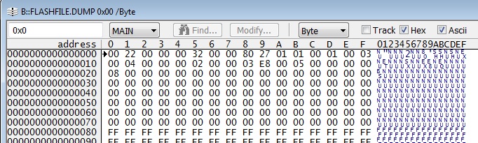
-          Run again the same .cmm file


Question 1 : Is this test protocol correct ? Currently, I haven’t implemented the solution to set  the

                        GPIOs used for the Boot Mode configuration in the correct state.


Hereafter what occurs :

-          The Boot Parameter Table is copied in RAM at @ 0x00873680 which is the memorization address  in RAM by the BOOTLOADER  :

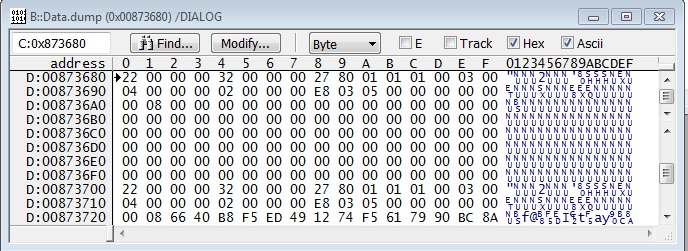
            The memorization seems correct considering the BOOTLOADER works in Little Endian.

-         Hereafter the resulting SPI registers configuration :

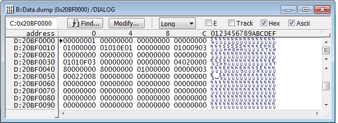
            The resulting configuration doesn’t  correspond exactly to the wanted one :

    • wanted C2Delay is 0. In the dedicated SPI register, C2Delay is set to 1.
    • SPI is not in MASTER mode and not ENABLED

   Except to those points, Configuration is available with the used FLASH NOR.


      Question 2 : what’s wrong in my configuration (Note that Main PLL is wanted to 1 Ghz) ?

                             In fact, I wonder if the Boot Parameter Table present in RAM is not a Boot Parameter Table by default !!!


      Question 3 : Shall the Boot Parameter Table be generated in Little Endian format ?

                              I have already done the associated test.

                              The Boot Parameter Table is not correctly memorized at @ 0x00873680 … content  of this zone is quite different of the real Boot Parameter Table

                              But in this case, SPI is in MASTER mode, ENABLED and Chip Select is in HOLD state


In all cases, the Boot Table is not copied in RAM or at an unknown location in RAM.

Note that Boot Table is generated using successively hex6x, bconvert64x and b2i2c.

Boot Table in FLASH SPI is set at @0x0800.

Without any more informations, I can"t investigate any more. Thanks a lot for your future answer 

Regards


Alban

  • Hi Alban,

    I've notified the RTOS team. Their feedback will be posted here.

    Best Regards,
    Yordan
  • Hi Yordan,

    I haven't yet received a feedback from the RTOS Team.

    Could you please ask them to give me an answer as soon as possible ?

    Indeed, I can't investigate any more as I have no mastery on the BOOTLOADER software debugging.

    It becomes very urgent for me.

    Regards

    Alban
  • Hi Alban,

    I've escalated this internally.

    Best Regards,
    Yordan
  • Alban,

    SPI Boot example has been provided on the wiki article Keystone Bootloader and Resources. Please refer to that example for details. Boottable, Boot parameter format is provided in that example.
    processors.wiki.ti.com/.../KeystoneI_Bootloader_Resources_and_FAQ

    If you have not implemented the GPIO based solution to setup the DEVSTAT, the ideal way to test this is to connect to the DSP core then flash the boot image to the SPI NOR flash and do a CPU reset and then unlock KICK registers and set the DEVSTAT to the correct value. Now you can run the bootloader as if the CPU is coming out of reset.

    Also, if you have a boot image, we recommend that you test the booting on the EVM and then test this on the custom hardware as we can only help you if report issues that we can reproduce in our environment.

    Please review the examples and let us know if you have any further questions.

    Regards,
    Rahul
  • Hello Rahul,

     Although I read carefully the various BOOT examples, it doesn’t currently work.

     Find hearafter an update of the encountered problem  :

    Boot Parameter table is the following :

    BootParamConfig = {   

          0x0028,     /* Table length = 40 */

          0x0000,     /* Checksum : no checksum verification by RBL */

          0x0032,     /* SPI Boot mode = 50 */

          0x0000,     /* Port Num : Not Applicable */

          0x4028,     /* PLL Configuration MSW : PLL mode, PLLM = 40, PreDiv = PostDiv = 2 */

          0x0202,     /* PLL Configuration LSW : PLL mode, PLLM = 40, PreDiv = PostDiv = 2 */

          0x0001,     /* Load Type : Boot Table Load */

          0x0018,     /* Address Width : 24 Bits */

          0x0004,     /* Operational mode, 4-Pins */

          0x0002,     /* Chip Select used = CS0 */

          0x0002,     /* Standard SPI mode : CPOL = 1, CPHA = 0 */

          0x0001,     /* Setup time between chip assert and transaction */

          0x03E8,     /* CPU Frequency MHz : 1 GHz */

          0x001B,     /* SPI Bus Frequency MHz : 36 ns */

          0x0302,     /* SPI Bus Frequency KHz : 36 ns */

          0x0000,     /* First Address to read from, MSW : 0    */

          0x0800,     /* First Address to read from, LSW : 2048 */

          0x0000,     /* Next Chip Select (Used only in boot config mode) */

          0x0000,     /* Next Read Address MSW (Used only in boot config mode) */

          0x0000      /* Next Read Address LSW (Used only in boot config mode) */     

    };


    This Table configures :  Main PLL set to 1 GHz  (CLCKIN = 100 MHz)

                                               Bus SPI with a 1 bit transfer period set to 36 ns

                                               Boot Table located  at @0x0800 in Flash SPI

    This PLL and SPI configuration havs been already validated by a Test software  … it works in a nominal state.


    Hereafter what occurs :

    -          The Boot Parameter Table is copied in RAM at @ 0x00873680 which is the memorization address  in RAM by the BOOTLOADER.

    -          PLL and SPI are correctly configured

    -          The Boot Table is not copied from Flash SPI to RAM (@0x00810000 in Local S2 RAM)

    -          The register BOOTCOMPLETE remains  to value 0x00000000, meaning BOOTLOADER is always active.

    In fact, the BOOTLOADER seems to execute in loop the same part of code and stays always within.


    Boot Table is generated from a .ELF file using successively following Tools : hex6x, bconvert64x and b2i2c     


    Question 1 : Does it exist an erroneous parameter in my “Boot Parameter table” ?

    Question 2 : Does it exist an error in the processing of Boot Table generation ?


    Regards

     Alban

  • Hello Rahul,

    I used the Board FMC667 from 4DSP as Evaluation board.

    regards

    Alban
  • Alban,

    thanks for reviewing the examples and providing more insight into your boot situation:

    Can you run the debug GEL provided here and provide the output when the boot fails:
    processors.wiki.ti.com/.../Keystone_Device_Architecture
    Note: Ensure no other GEL file runs before running the debug GEL file.

    It will help evaluate where the boot has failed and provided the PC value so that we can look at the ROM bootloader source to determine the issue.

    since the boot parameter table is copied and PLL and SPI clocks are set, I think there is no issues with DEVSTAT or Bootmode settings but can you please provide that for my analysis. Have you measured the SPI clock and observed if it is set to the correct value. If the SPI clock is out of spec then it could explain why the boot table is not being copied. How did you append the boot parameter table using romparse or using your own utility? How was the offset value for the boot table address computed in the boot parameter table.

    Can you provide your boot binary here so that I can look at the format and provide feedback.

    Regards,
    Rahul
  • Hello Rahul,

    I don't use GEL file as I don't use CCS. I use TRACE32. But,  I can give you some informations.

    DEVSTAT register is set to 0x0000260D manually by TRACE32.

    I check the Main PLL, which is at 1Ghz : it is OK as it is the wanted value.

    I check also the register SPIFMT0  = 0x00020508. PRESCALE value is 05, implying a SPI bus clock to 36 ns. OK as it is the wanted value. Note that 36ns leads to SPI bus Clock = 27.77 Mhz

    Such PLL and SPI configuration works when I use it in a test software !!!

    The BOOTLOADER loops at PC= @0x20B0A350. In another post, it is said it corresponds to a function dealing with SPI Transfer.

    When I stop the execution, I can see the SPIBUF register contains some received data.

    But, those received data seem to be always the first four bytes of the BOOT software.

    Find enclosed within the BOOT software : 

    SBoot_Sw.dat

    Thank you for the time spent to answer my questions

    Regards

    Alban

  • Hi Rahul,

    To Complete my answers ....

    You can see the Boot parameter Table in a previous post :
    Boot Parameter Table is set at @0x000000
    Boot Table is set at @0x000800 ( 0x0000, /* First Address to read from, MSW : 0 */
    0x0800, /* First Address to read from, LSW : 2048 */ )

    For remind, Boot Table is generated from a .ELF file using successively following Tools : hex6x, bconvert64x and b2i2c

    regards

    Alban
  • Hi Rahul,

    Could you please answer to my questions .... Really, i don't know in which direction to investigate.

    Find hereafter my process to generate the SBoot_Sw.dat

    Original file :    SBoot_Sw.out

        First command :    <TiInstallationDir>/ccsv6/tools/compiler/ti-cgt-c6000_8.0.3/bin/hex6x.exe ./SBoot_Sw.rmd

                                          RMD file is as follows : 

    -------------------------------------------------------------------------------------------------------------------

    C:\Users\F553417\Desktop\HDF\BOOT\GenBootTableBoot\SBoot_Sw.out
    -a
    -boot
    -e _c_int00

    ROMS
    {
    ROM1: org = 0x800, length = 0x80000, memwidth = 32, romwidth = 32
    files = { C:\Users\F553417\Desktop\HDF\BOOT\GenBootTableBoot\SBoot_Sw.btbl }
    }

    -------------------------------------------------------------------------------------------------------------------

    Second command :               <TiInstallationDir>/mcsdk_2_01_02_06/tools/boot_loader/ibl/src/util/bconvert/bconvert64x.exe  -be

    ./SBoot_Sw.btbl  ./SBoot_Sw.btbl.big

     Third Command :                 <TiInstallationDir>/mcsdk_2_01_02_06/tools/boot_loader/ibl/src/util/btoccs/b2i2c.exe

                                                     ./SBoot_Sw.btbl.big  ./SBoot_Sw.dat


    I have some more questions : As you can see, i don't use utilities, as ROMPARSE, to convert file in CCS format as I don't use Code Composer Studio.

                                                          Is the BOOTLOADER needs a CCS format to work normally or CCS format is only available if we use Code Composer Studio ?

                                                          Is the initial file .OUT file is in fact a .ELF file ?

    Regards

    Alban MICHELANGELI

  • Alban,

    Sorry for the delayed response, I was side tracked due to some software release blocking activity. Let me start from where we left off.
    The DEVSTAT value appears to be configured correctly for SPI boot in little endian mode with CS0 and parameter table index 0 with 24 bit addressing and 4 pin mode and data latching on falling edge which appears to accurate. Also, as you mentioned the software is stuck at SPi transfer based on your PC as you mentioned. If you are using romparse utility to append the boot parameter table then offset 2048 (0x800) offset is correct because romparse appends 8 boot parameter tables and each table is size 0x100 so the boot table should occur after all the boot parameter tables. In your flsh binary can you see if the boot table is starting at 0x800 offset.

    In your case, if you don`t use ROM parse then, I am not sure if the 0x800 offset is correct. If there is only one boot parameter table then your offset should be equal to the sizeof (boot parameter table) which I think is 0x100. In the steps described above, you have not specified how the boot parameter table was appended to the boot table. ROM parse is the utility

    Also, Can you clarify how you are flashing the image to the SPI NOR. The examples we provide uses the SPI Writer from the SDK. It is important to get the format in which the SPI image needs to be flashed on the NOR flash which is why we bit flip the image and then pass it to the SPI Writer.

  • Alban MICHELANGELI said:
     Is the BOOTLOADER needs a CCS format to work normally or CCS format is only available if we use Code Composer Studio ?

    Yes, the boot table needs to be in CCS format only so that it can be loaded in memory using CCS Memory loader for the SPI Writer to read and flash to the boot media.

    Alban MICHELANGELI said:
      Is the initial file .OUT file is in fact a .ELF file ?

    The initial .out is in ELF format if you are using CGTtools 7.4.x and later, it will generate .out in ELF by default. The .out file is converted to boot table using the hex6x utilty, all the other steps are required only to get the image in the correct format for flashing.

    romparse is the utility that we provide in the SDK to append boot parameter table to the boot table so that default boot setting can be changed.

  • Hello Rahul,

    Thank you for your answer.

    We don't use Code Composer Studio (CCS) to Flash files data inside the FLASH SPI NOR.  We use TRACE32 with a LAUTERBACH probe.

    We use TRACE32 tools to flash data in aforementioned flash. These tools flash directly raw data byte after byte.  That's the reason why CCS format is not compatible with our process.

    Firstly, we flash the Boot Parameter Table at @0x000000.

    Then and independently, we flash the Boot Table at @0x000800. It must be raw data and not the CCS format.  

    Now, I understand why the Bootloader is unable to load our BOOT software in RAM : it's because  up to now, I didn't flash the Boot Table in a raw data format.

    Is my analyzis right ?

    Do you have the tool which allow to get the file containing the Boot Table in raw data format ?

    Regards

    Alban MICHELANGELI