Hi,
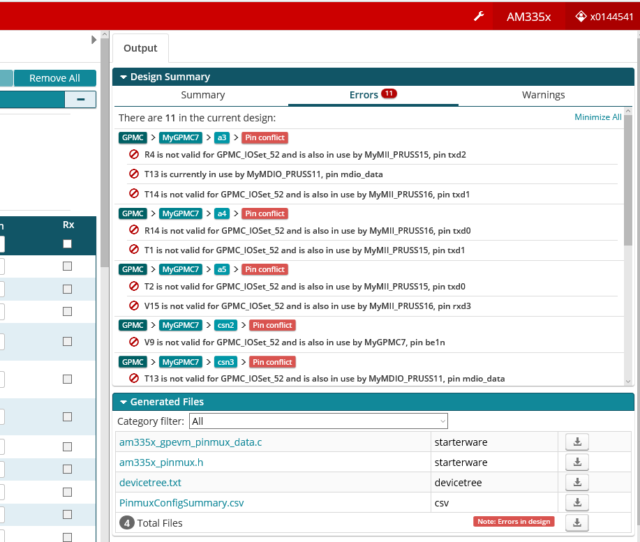
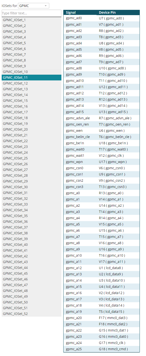
PINMUX doesn't let me use pin T17 for GPMC signal "Wait0" when I use MII1_PRUSS1, although I haven't used "COL signal" with this pin.
Is this bad working of PINMUX software or is that a restriction when using PRU?
Thank you so much.
Regards
Hi,
PINMUX doesn't let me use pin T17 for GPMC signal "Wait0" when I use MII1_PRUSS1, although I haven't used "COL signal" with this pin.
Is this bad working of PINMUX software or is that a restriction when using PRU?
Thank you so much.
Regards