This thread has been locked.

If you have a related question, please click the "Ask a related question" button in the top right corner. The newly created question will be automatically linked to this question.

Linux/Dra750: USB3.0 speed

Part Number: DRA750

Tool/software: Linux

Hi all,

we are using DRA7xx_GLSDK_7.04.00.03 to develop our custom board.

We have two custom board using dra750 as CPU, and connect their usb1(3.0 port) together.

One is setting to host mode, while the other is setting to device mode.

When we modeprobe g_mass_storage.ko on the device one,

Host will detect a mass storage: /dev/sda,

(refer to: processors.wiki.ti.com/.../Linux_Core_DWC3_User's_Guide)

Then we partition and formate /dev/sda and mount it to a directory.

Finally we use dd command to create a file in that directory.

The problem is that it seems operating in high speed mode, not super speed.

How to make it to work in super speed or any setting can force both usb1 ports to work in super speed?

Pleas kindly give me some advice, thank you so much.

  • Hi all,

    sorry, i need to make some correction.

    "One" custom board with two dra750 CPU, and thier usb1 ports are connected together.

    So we are not using cable to connect usb ports, thier pins are connected directly.

    Thanks again for taking your time.

  • Hi Shawn,
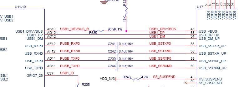
    Can you post the part of schematic diagram related to USB?
    Regards,
    Stan
  • Hi, Stan,

    please refer to the attachment.

    Thank you so much.

    4555.USB.pdf

  • Hi Shawn,

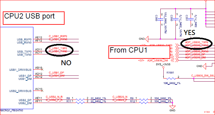
    Do you have the AC-coupling capacitors on the J6 CB similar to below:

  • Hi Stan,

    Thanks for your reply.

    We have them on the CPU1 tx side, but don't have them on the CPU2 tx side.

    After you point out this, we also tried to add them at CPU2 tx side, but it still works in high-speed.

    If you have any thoughts, please kindly tell us.

    Thank you so much.

  • Shawn,

    I would like to check the schematic part with CPU1. Also, can you point out the Ac capacitors on the schematic. You can email the documents to me if you don't wish to share them here.
    I don't recall anything specific for now.
    Did you try other debugging? For example switching to USB2ETH (port B of the switch) and try to connect?

    Regards,
    Stan
  • Hi Stan,
    I have sent it to you.
    I didn't try USB2ETH because our project schedule is now focus on USB to USB.
    Thanks for your help.
  • Hi Stan,
    thanks for your reply.

    I had found a procedure to let CPU1 detect CPU2 as a super speed device.
    It need to change the host/device mode of both side twice.
    1. do the things I post in thread, then CPU1 has a high-speed storage attached.
    2. change the mode of CPU1 from host to device.
    3. change the mode of CPU2 from device to host.
    4. change the mode of CPU1 from device to host.
    5. change the mode of CPU2 from host to device.
    After these steps, CPU1 can detect CPU2 as a spuer speed device.

    I find that USB1 has two hubs,
    one is 2.0 and the other is 3.0.
    If the gadget is attached to 3.0 hub,
    It can work in super speed.

    Is there a way to force the gadget to attach 3.0 hub?
  • Hi Shawn,

    I have forwarded your query to USB driver expert.

    Regards,
    Yordan
  • Hi Yordan,
    thanks for your help,
    any update?

    We have another question.
    We need to measure the eye diagram.
    Refer to processors.wiki.ti.com/.../USB_General_Guide_Linux_v3.8
    Is "test_packet" for generating the eye diagram?
    Is this function support USB3.0?
    Should i open another thread to ask?
    Thank you.
  • Hi Stan

    The USB3.0 does not use test_packet for eye compliance test. The "test_packet" generation is basically for USB2.0 High speed.

    The USB3.0 complainance suite shall support eye diagram test, for USB3.0 which use various compliance pattern (CP0, CP1, CP2, etc), which shall be transmitted continuously or until a ping LFPS is detected at receiver.

    refer to USB3.0 specification section 6.4.4.

    Entry to the Compliance Mode is described in Chapter 7. This initiates the transmission of the
    pseudo-random data pattern generated by the scrambled D0.0 compliance sequence. SKPs are not
    sent during the compliance pattern. The compliance pattern shall be transmitted continuously or
    until a ping LFPS (refer to Section 6.9) is detected at the receiver. Upon detection of a ping LFPS,
    the compliance pattern shall advance to the next compliance pattern. Upon detection of a reset, the
    compliance pattern shall be terminated. The compliance pattern sequences are described in
    Table

    Compliance Pattern Value Description
    CP0 D0.0 scrambled A pseudo-random data pattern that is exactly the same as
    logical idle (refer to Chapter 7) but does not include SKP
    sequences
    CP1 D10.2 Nyquist frequency
    CP2 D24.3 Nyquist/2
    CP3 K28.5 COM pattern
    CP4 LFPS The low frequency periodic signaling pattern
    CP5 K28.7 With de-emphasis
    CP6 K28.7 Without de-emphasis
    CP7 50-250 1’s and 0’s With de-emphasis. Repeating 50-250 1’s and then 50-250 0’s.
    CP8 50-250 1’s and 0’s With without de-emphasis. Repeating 50-250 1’s and then
    50-250 0’s.

    Regards
    Ravi