This thread has been locked.

If you have a related question, please click the "Ask a related question" button in the top right corner. The newly created question will be automatically linked to this question.

CCS/AM1705: Error : Erasing SPI failed

Part Number: AM1705
Other Parts Discussed in Thread: OMAP-L137

Tool/software: Code Composer Studio

Hi,

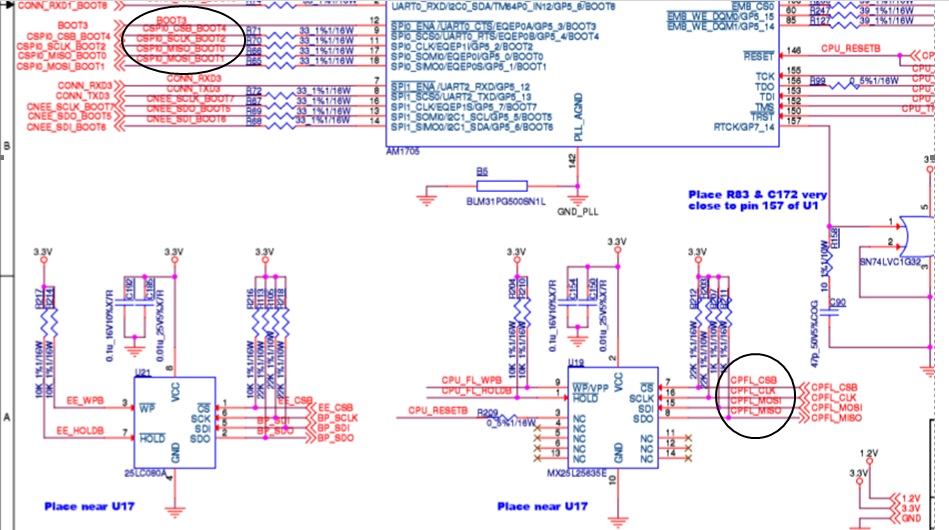
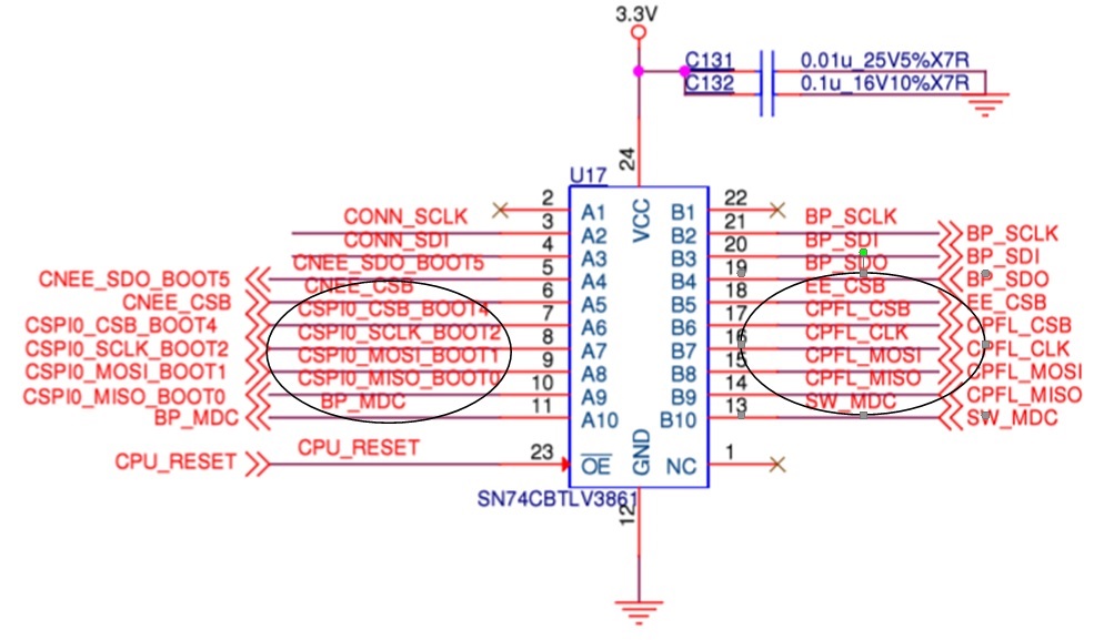
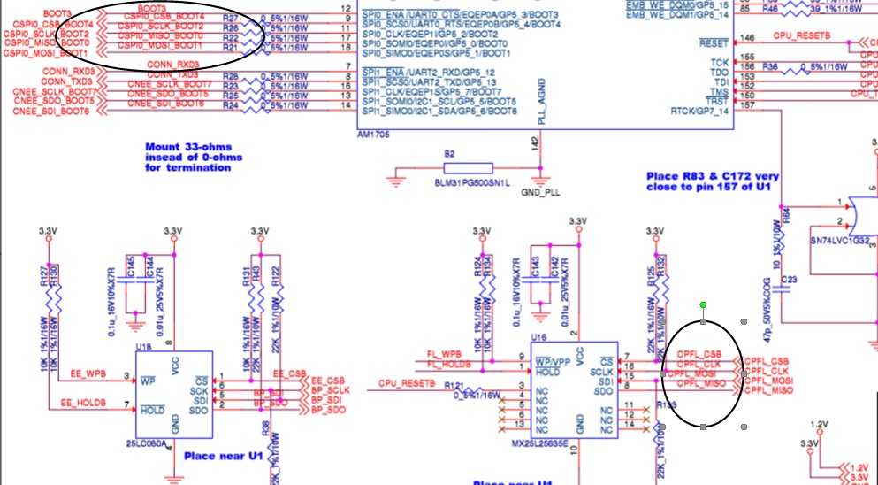
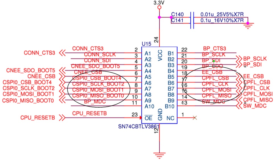
We have made a custom AM1705 board with IC Part Number AM1705DPTPA3 and are using SPI flash for booting. Flash IC part No is Macronix MX25L25635E.

We are using Code Composer Studio v4 and XDS100v2 TI 14-pin JTAG Emulator Part No TMDSEMU100V2U-14T for writing the SPI flash 

In the ROM bootloader version check of our AM1705 IC the memory view is displaying text d800k005

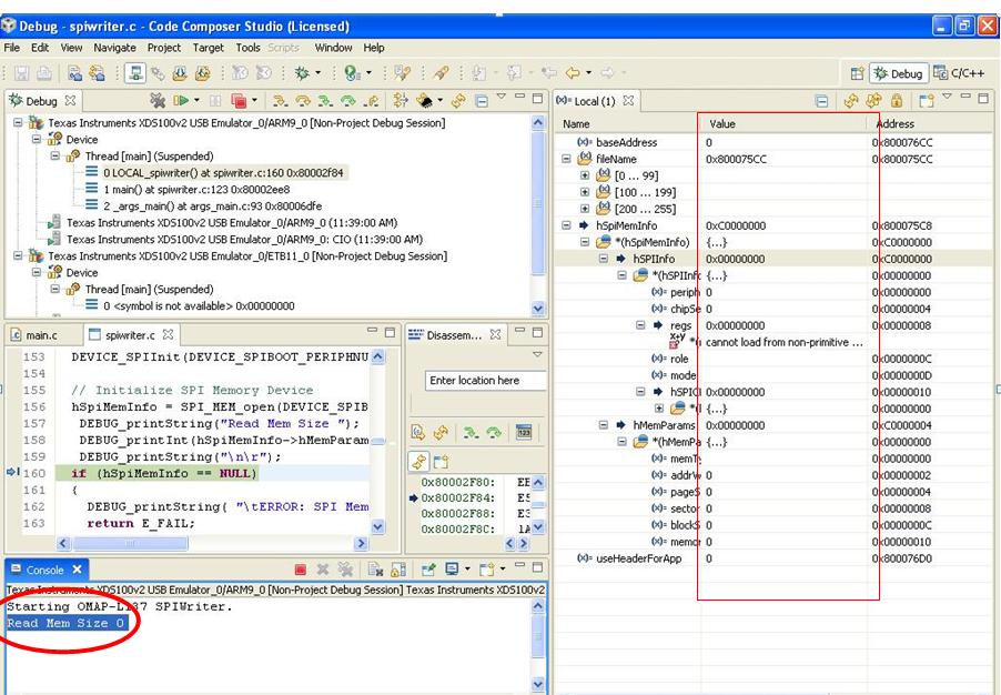
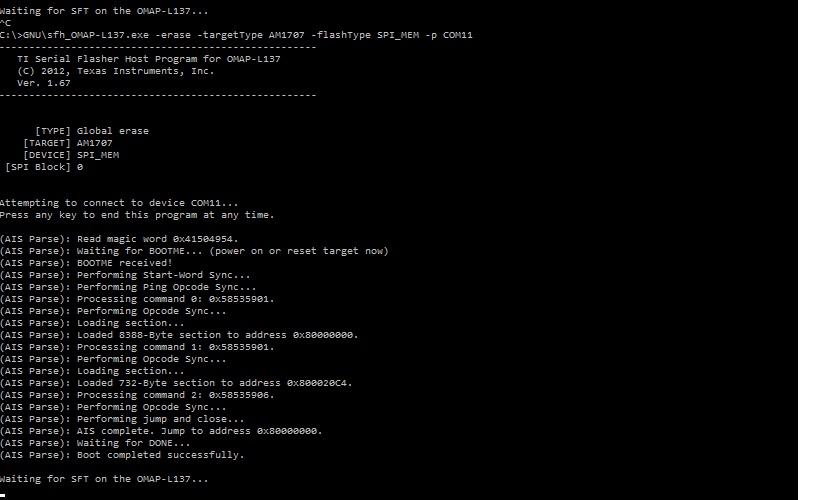
 I have downloaded the OMAP-L137_FlashAndBootUtils_2_40.tar.gz and loaded the spiwrite.out file created from the above CCSv4 project & run the code. 

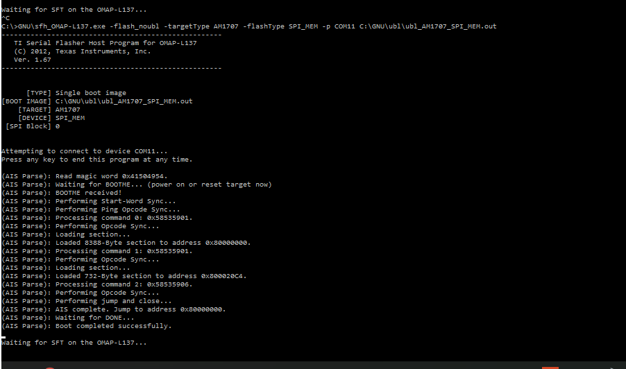
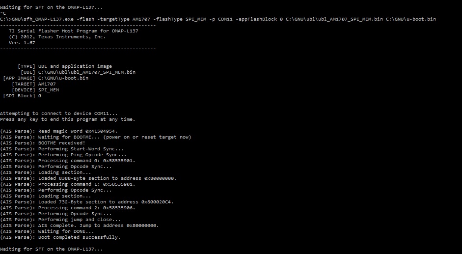
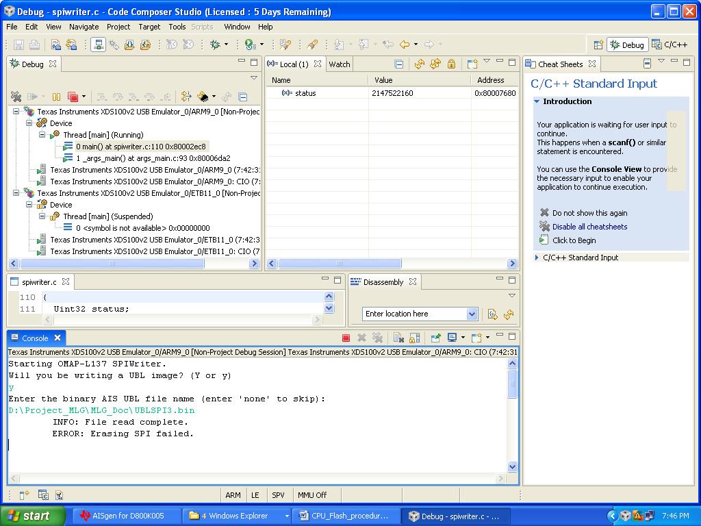
then the spiwrite application ask for ARM UBL file, then when I load the ARM UBL provided by OMAP-L137_FlashAndBootUtils_2_40.tar.gz  then it gave me " Error : Erasing SPI failed " as shown in the Pic below

Which SPI writer should be use or any modifications are needed to be done for writing the SPI flash on the custom AM1705 board ?

Please help me to solve the above issue.

Thanks & Regards,

Sandesh

  • Hi,

    I've notified the RTOS team. Their feedback will be posted here.

    Best Regards,
    Yordan
  • the SPI flash writer in the Serial flash and boot utilities was created and tested with W25X32VSFIG (32 M bit flash device) that is provided on the TI evaluation platform. YOu need to compare the MAcronix flash command set with the Winbond Flash command set and modify the code accordingly

    Regards,
    Rahul
  • Hi Rahul,

    Thanks for the reply.

    Can you please tell us in which file of OMAP-L137_FlashAndBootUtils_2_40.tar.gzI should I make the changes for the Macronix flash and what parameters should I change in the file

    Regards
    Sandesh
  • Sandesh,

    Import the SPi Writer project into CCS and you will be able to see all the files linked to the project. In that project Locate the file spi_mem.h which has the SPI_MEM_TYPE And SPI FLASH COMMAND table compare this with table provide in your flash datasheet.

    Since your erase failed, I suspect that the command used on your flash is different. Other thing to check is is you SPI connected in 4 pin mode?
    If yes, do you see the clock and the SPI chip select go low when the erase command is sent?

    Regards,
    Rahul
  • Hi Rahul,

    As per your suggestion we have compared the spi_mem.h file with flash datasheet and we found that the commands are same.

    The Flash MX25L25635E on our board is connected with SPI0 port of the AM1705 in 4-pin mode i.e SPI_CS, SPI_CLK, SPI_MOSI, SPI_MISO. The Hold, Write_protect, Reset pin of the AM1705 are pulled up to 3.3V.

    The AM1705 IC is configured in JTAG mode by keeping the Boot pins 0,1,2,3,7 as 0,1,0,0,1 respectively as per given in the AM17XX bootloader application notes

    In the CCSv4 tool we build the project using the OMAP137 Boot and flash Utilities files and connected our custom AM1705 board with the PC

    While doing the above operation we monitored and tried to capture the SPI_CS and SPI_CLK signal coming out of the AM1705 IC on the board using the oscilloscope, but we did not see the SPI_CS signal going low.

    Actually we have our custom older version boards with AM1705BPTP3 (part now obsolete) which has the same flash with same schematic and circuit on which if we try to write the spi , it gets successfully written, but in the new board we have the latest AM1705DPTPA3 IC with which we are getting this errors

    Please suggest some solution

    Thanks and Regards,

    Sandesh

  • Thanks for clarifying Sandesh. This doesn`t appear to be a software issue to me given that the same code worked on your earlier version of the platform. The SPI_CS is required for flash to recognize that the data/command transmitted is meant for it or not.

    Let us try to identify difference between the old and the new board to root cause this issue. I have looped in my hardware colleague to also provide his inputs. From software perspective the following issues could make a difference. Are there any hardware differences other than the silicon revision.

    * Are you using a GEL file to initialize the system clocks and PSC. The SPI power domain may be power on by GEL file.
    * Is it possible the the SPI_CS pin is being muxed to GPIO or some other setting?
    * Is there some pull up settings on the CS that is causing the pin to remain high ?
    * Have you been able to replicate this on more than 1 board? This will eliminate soldering or board specific issues.

    Regards,
    Rahul
  • Sandesh,

    As Rahul mentioned in his post, we would like to know the difference between the old design and new design. Also please answer the questions in Rahul's post to identify the cause of chip select signal not getting low.

    Regards,
    Senthil
  • Hi Rahul, Senthil,
    Thanks for replying
    From hardware point of view
    1. There is a pull up on the SPI0_CS pin in the new board same as in older version board. The pull up resistor value is 22Kohm
    2. We have 2 numbers of newer version board and we are getting same error on both the boards
    3. The SPI0 port on the AM1705 is dedicated to the SPI Flash only and it is not multiplex to any other SPI peripheral or GPIO
    Schematic for new board
    Schematic for older board
    On the firmware side, we tried to debug and run the code in step by step using the Code Composer Studio,
    Here is what we are getting the issue
    Board with new version
    and Board with older version
    Please reply
    Best Regards,
    Sandesh
  • Hello Sandesh,

    Could you please try remove the 22K pullup on CS line and check the SPI operation ?

    Regards,
    Senthil
  • Hi Senthil, Rahul,

    I removed the Pull up from the SPI_CS pin and tried to program the SPI flash, 

    this time also it did not get programmed.

    It seems that the AM1705 is getting hanged during programming because it did not even showed the message  of  "Erasing SPI failed"

    We added debugs in the code before and after the spi erase function to debug the issue, but the code was getting stuck before the erase operation and it did proceed further. (The file read operations before erasing use to get  successful i.e "file read complete")

    I tried it programming the newer version board many times but every time the AM1705 processor use to get hanged before erase operation and the CCSv4 software use to stay in Running mode for long time untill we terminate the operations

    But the we could see the same debugs in our older version board  which has the AM1705B, 

    We are using the XDS100v2 JTAG -14 pin debugger for writing SPI flash

    Do we need to take newer one? if yes, please let us know

    or do we need to make any firmware changes for the newer AM1705D IC in the code?

    Please reply

    Thanks & Best Regards

    Sandesh

  • Sandesh,

    What frequency you configured the SPI ? Could you try with lower frequency and see the issue still exist ?

    We would check on the software and update you.


    Regards,
    Senthil

  • Hi Senthil, Rahul,

    We have configured the frequency of the SPI as 1 MHz,

    We even changed the frequency to the lower value, but the issue still exist

    We have got a following post similar to our issue but it deals with the OMAP-L138E processor and we are facing the same issue with AM1705

    In our case the AM1705 gets hanged at  " else if (hSPIMemInfo->hMemParams->memType == SPI_MEM_TYPE_FLASH) "  and the 

     CCS cannot read at the specific adresses. So the problem is, that it does not goes into the erasing and programming section as it always drop out at:

    else if (hSPIMemInfo->hMemParams->memType == SPI_MEM_TYPE_FLASH)

    Please reply 

    Thanks & Regards,

    Sandesh

  • Hello Sandesh,

    I am not sure why the device is getting hanged when you are accessing SPI. Also there is no software change required for new revision device. Could you please try SFH utility to write the image into SPI flash and see if it succeeds. This would help us to isolate the issue.

    processors.wiki.ti.com/.../Serial_Boot_and_Flash_Loading_Utility_for_OMAP-L137

    Regards,
    Senthil
  • Hi Senthil,

    As per your suggestion I tried SFH Utility to write the image into the flash

    Here are few images

    The above operations are getting halted at the " waiting for SFT on the OMAP-L137..."

    At the end lines of all the above 3 operations it is saying Boot completed successfully for which just for confiming while doing the above operations, I tried to monitor the SPI0 signals of the AM1705D IC on which the flash is connected using oscilloscope specially the SPI0_CLK signal, but I did not see any waveforms or clk signals coming out of the AM1705D IC,

    So I am confused whether the flash is really getting erased and written using the serial flash writer or not?

    Please reply


    Thanks & Regards

    Sandesh

    Hi Rahul, Senthil,

    Please help us solve this issue, since our project is already delayed 

    Best Regards,

    Sandesh