This thread has been locked.

If you have a related question, please click the "Ask a related question" button in the top right corner. The newly created question will be automatically linked to this question.

66AK2G02: difference for unused pin(AE6, AE9, AD6, AD9) between ICE board and datasheet.

Part Number: 66AK2G02

Dear Champs,

Could you please confirm if datasheet is right for unused pin?

I'm confused as I found a difference between datasheet and ICE board.

I found below unused pins should be connected to GND when 1 x 16bit DDR3 used, 

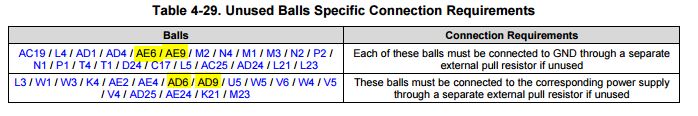
But, I found DDR3_DQS2_P(AE6), and DQS3_P(AE9) are connected to DVDD_DDR and DDR3_DQS2_N(AD6) and DDR3_DQS3_N(AD9) are connected to GND in ICE board schematic.

Could you please let me know what is correct?

Thanks and Best Regards,

SI.

  • Hi,

    Use the data manual recommendations. The rule is to connect *_N pins to power supply & *_P pins to GND, as described in the datasheet.

    Best Regards,
    Yordan
  • Thanks,

    For DDR_CLK, DDR_CLK_N(AD24) is connected to GND, and DDR_CLK_P(AE24) is connected to VCC according to Table 4-29.
    Could you please check these pins also?


    Thanks and Best Regards,
    SI.
  • Hi SI,

    Also follow the data manual on these pins. The pull up/pull down for the differential inputs are mainly to keep these signals in a steady state and avoid any chatter on the lines. This will avoid any extraneous clock signals inside the K2G.

    Regards,

    Bill

  • Hi Bill,

    I'm still confused and want to double confirm Table 4-29 again.

    For DDR3_DQS, in datasheet Table 4-29, it is said DDR3_DQS_P is connected to GND, and DDR3_DQS_N is connected to VCC. But, also in datasheet Table 4-29, it is said DDR_CLK_P is connected to VCC, and DDR_CLK_N is connected to GND.
    I want to check this again because there is no coherence and DDR3_DQS_P is connected to VCC and DDR3_DQS_N is connected to GND in ICE board schematic.


    Thanks and Best Regards,
    SI.
  • Hi SI,
    The thing to remember is that these are differential signals. Pulling one side up and one side down will hold the input in a stable state. For clocks and DQS it doesn't matter which side is up and which side is down.
    Regards,
    Bill