This thread has been locked.

If you have a related question, please click the "Ask a related question" button in the top right corner. The newly created question will be automatically linked to this question.

AM4378: Issues booting from MMC0 interface

Part Number: AM4378
Other Parts Discussed in Thread: TIDEP0014,

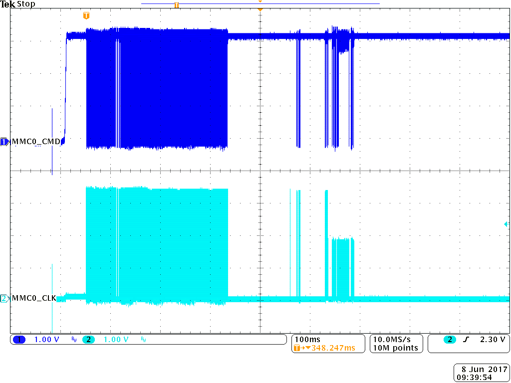
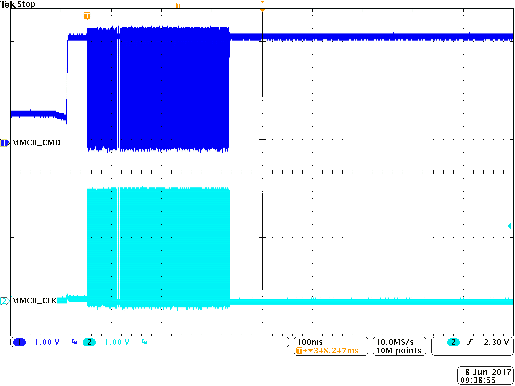
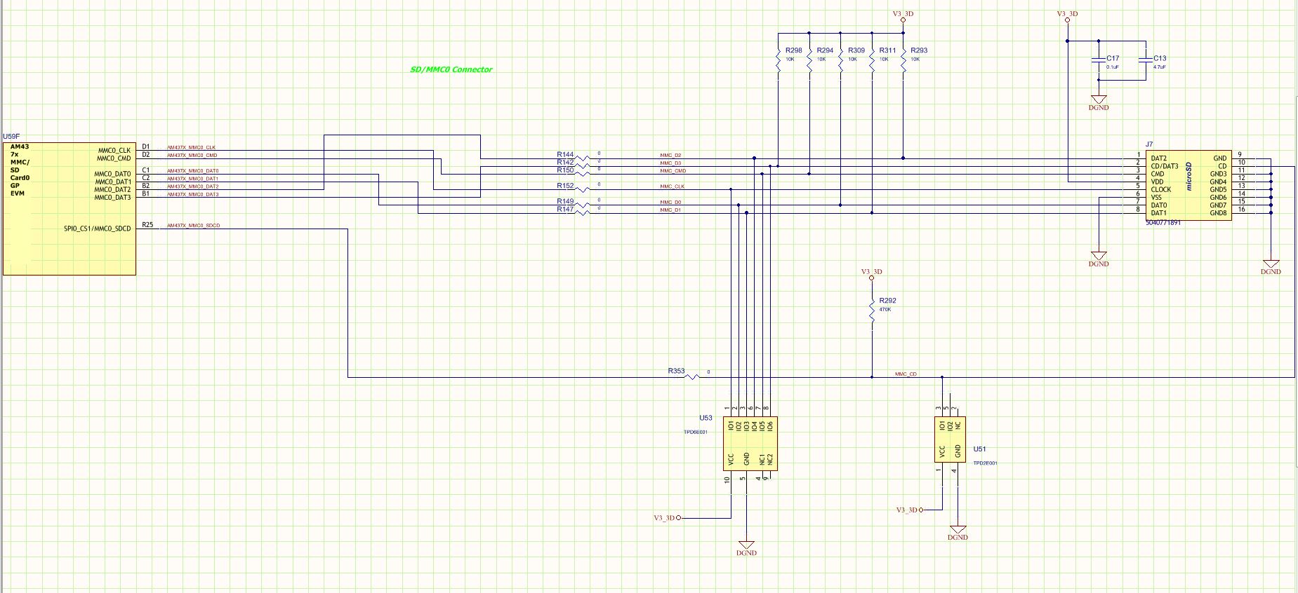
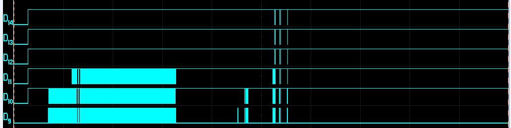
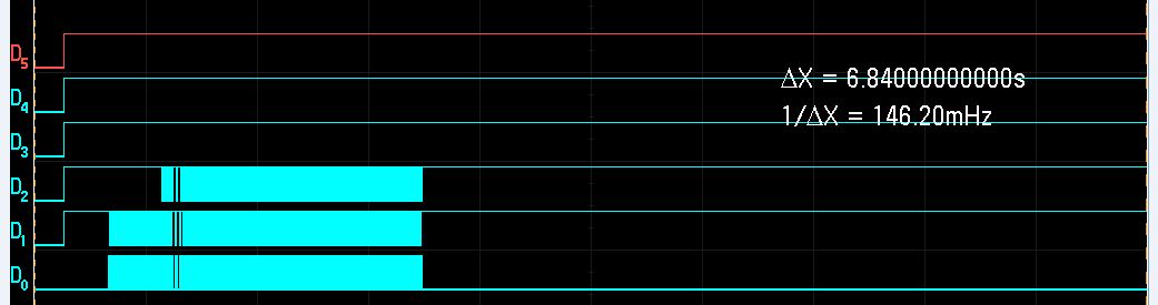
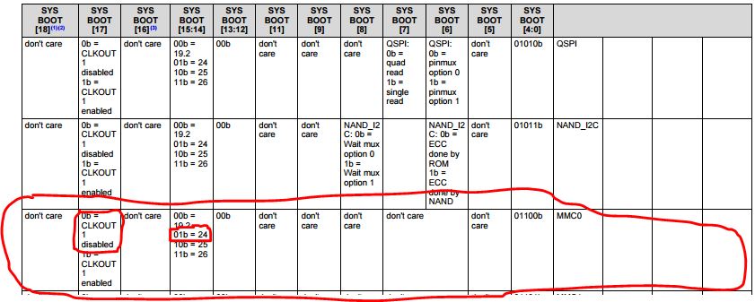
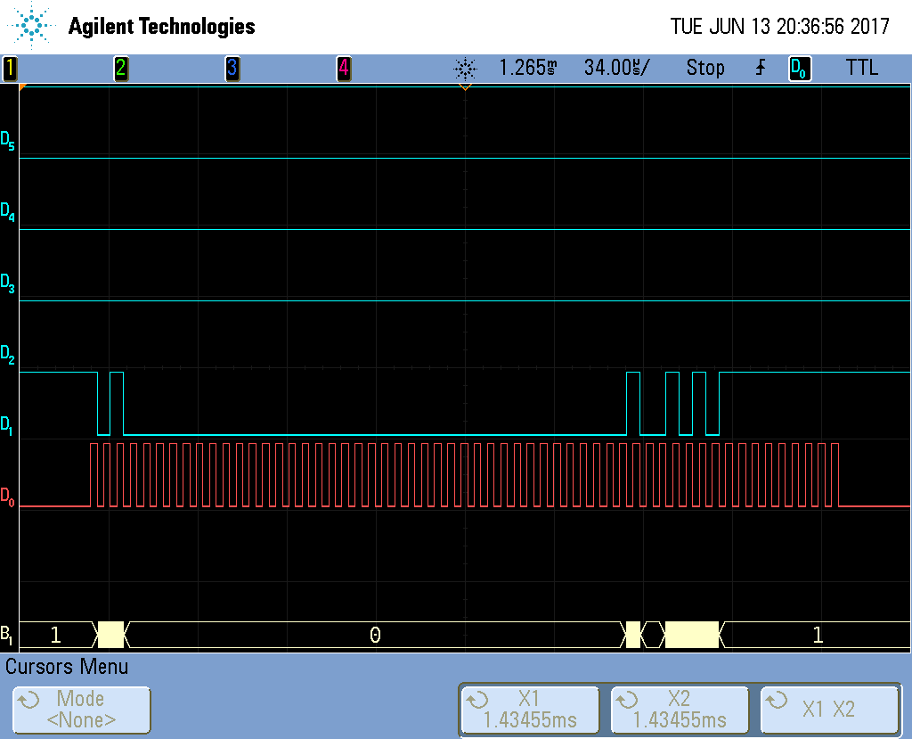
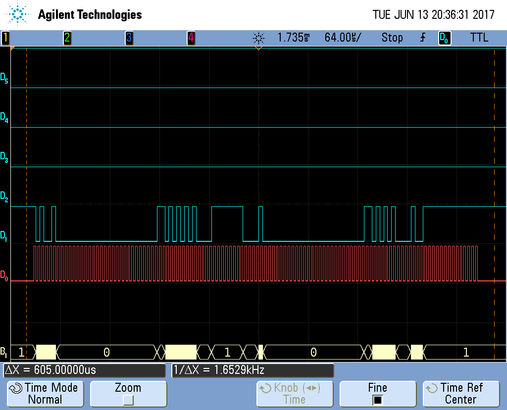
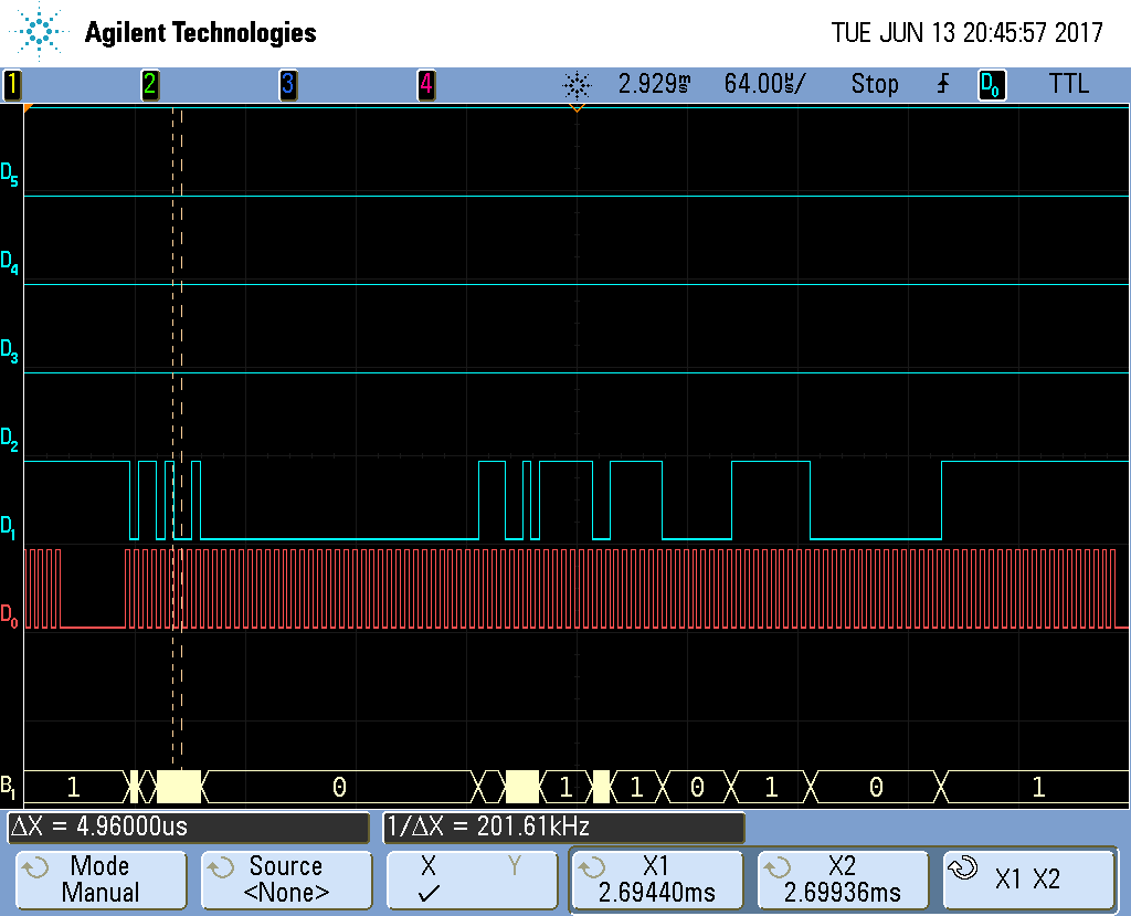
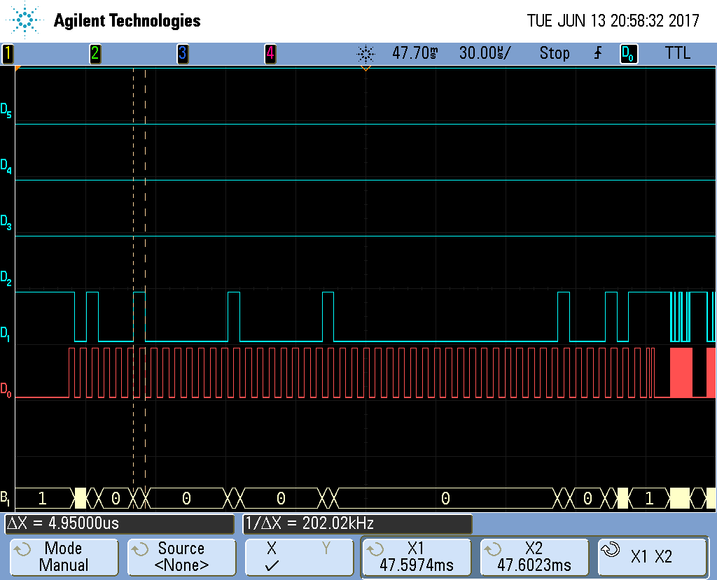
We are trying to boot into a linux operating system using the MMC0 interface.  It appears that the processor starts and does the intitial interaction with the MMC0 port, it seems that it does communicate with the SD card.  The processor then goes to a higher speed clock (25MHz) and it will still communicate to the SD card using the CMD line, data looks to be sent on the D0 line but it will not go beyond this.

I am not sure what else to look at for debugging this issue, we have double checked and verified the bootstrapping pins and they are correct.  Any help would be greatly appreciated.

  • Brian, I assume this is a custom board? The schematic checklist also has some tips
    processors.wiki.ti.com/.../AM437x_Schematic_Checklist

    Especially check for the series resistor on MMC_CLK. Can you get a scope shot of the clock during boot?

    Regards,
    James
  • Yes, this is a custom board, but we based the design on the AM437x GP EVM.  I've attached scope shots from our custom board and the AM437x GP EVM showing the MMC0_CLK and MMC0_CMD signals during startup.  It appears that the initialization happens the same on both boards but on our custom board nothing happens after that, as compared to the AM437x GP EVM you can see the CLK and CMD signals continue after the initialization.

    AM437x GP EVM Startup

    Custom Board startup

    Here is what the schematic looks like for the microSD connector to the processor;

  • Here are scope shots that show all data lines;

    AM437x GP_EVM startup

    Custom Board Startup

  • Brian,

    I have a couple of questions to baseline understanding of your board setup.

    What is your SYSBOOT configuration?

    What reference clock frequency is used?

  • Our SYSBOOt configuration is currently set to: 01100b MMC0

    Clock frequency is set to: 01b = 24MHz (This should be the same as the TIDEP0014 development kit that we have).
  • Thank you.  Just to clarify, your SYSBOOT configuration is below?

    SYSBOOT[17] = ?
    SYSBOOT[16] = don't care
    SYSBOOT[15:14] = 01
    SYSBOOT[13:12] = 00
    SYSBOOT[11:5] = don't care
    SYSBOOT[4:0] = 01100

    If you zoom into the logic analyzer traces of the MMC0 activity, are you seeing responses from the memory card to the CMD1 command from the AM437x or CMD55+ACMD41 command from the AM437x?

    Did the original burst of activity on the MMC0 interface actually last longer on your target hardware than on the EVM?  From the logic analyzer trace plot, it appeared to be a little longer (ie. more transactions), but it wasn't clear and I don't want to make assumptions.

  • Here is a screenshot of the SYSBOOT config, I just took a screen shot from the datasheet and highlighted the configuration.

    I can try and get some more scope shots of the responses, but as memory serves me I recall that we were getting the same responses during the initialization on the dev kit or on our custom board.  The initial interactions were taking place at maybe 300kHz or so, then the clock speed increased to 12MHz.  Following that is when our custom board no longer has interaction, on the dev kit it continues to read, and I think the clock speed increased again at this point to 50MHz. 

  • Adding some more information in regards to the MMC0 interface signals on the custom board.  The MMC0_CLK begins (the first three 'packets' in the image) at 250kHz, when the MMC0 interface starts transmitting data on MMC0_CMD the clock frequency changes to 200kHz.

    below is the first message transmitted on the MMC0_CMD line, there is no response to this message;

    The next message on the MMC0_CMD line does get a response, the data is in the image;

    Message 3 on the MMC0_CMD line looks to be CMD55, and there appears to be a response;

    Message 4 on MMC0_CMD is the ACMD41 message, it looks like there is a response to this as well;

    It appears that then a series of CMD55...ACMD41...CMD55...ACMD41 continues between the processor and the microSD card.  The last message on the MMC0_CMD line prior to changing clock speed from 200kHz to 12MHz is CMD9, asking for card specific data, to which it appears the card responds.

    The processor then sends CMD4 on the MMC0_CMD line, then changes the clock speed;

  • If you are seeing the MMC0 clock speed jump up to 12MHz, this should be indicative of the MLO (first kernel copied from SD Card to internal memory by ROM code) taking over and executing.  The ROM code (aka. boot ROM) reads the MMC interface in 1-bit mode and slowest clock speed to accommodate various memories.  This MLO then reconfigures the clocks to support reading u-boot out of the SD Card at a faster rate.  The MLO is executing out of internal memory.

    Is there any data coming out of the UART during this time?

    If the DDR timing or any of the clock configuration is off, then you may not see any output on the UART.  If data is coming out of the UART, I would look at DDR timings.

  • What settings should I use for the UART? and which UART should I connect to? I tried connecting once before and did not receive any messages, I was connected to UART0 with 115200,8,N,1
  • What does MLO stand for?
  • Not to confuse things, but MLO is the filename the ROM code looks for in the FAT filesystem for the SD Card.  It is a rename of SPL, which is Secondary Program Loader.

    http://processors.wiki.ti.com/index.php/The_Boot_Process

  • I am not able to get any communication information from the UART on our custom board.

    So where is the root of this problem, why are we not able to boot into the operating system that is on the microSD card?
  • I would imagine it is UART0 if your design is based on the GP EVM. I believe those are the appropriate settings.
  • One thing I was wondering if it could be causing our issues, on the development kit the DDR3 memory is MT41K512M8RH-125, which is 800MHz clock rate.  Unfortunately that DDR3 memory is obsolete and the manufacturer suggested alternate part is MT41K512M8DA-107 which is 933MHz clock rate.  Is the AM4378 processor compatible with 933MHz clock rate DDR3 memory?

  • Brian, let's ensure you are getting out of the ROM before trying to debug DDR issues. I have a few questions:
    -do you have JTAG access on your custom board? If you do, we can confirm how far into the boot process you are getting.
    -where is R152 physically located relative to the processor and card cage? Ideally it should be place as close to the processor as possible.
    -I saw your scope shots, but I'd like to see a zoomed in version on MMC_CLK (mainly at the high frequency where it is failing). We might need to adjust the value of R152 to ensure there are no reflections on the clock.

    Regards,
    James
  • - We do have access to the JTAG port, it is the same connector as J8 on the dev kit, we have the XDS2000 debugger.
    - R152 is located in nearly the same exact position as it is on the dev kit, I don't think we moved it.
    - I will follow up with a scope shot of MMC0_CLK when it is running at 12MHz. I did compare this with the same signal from the dev kit and nothing looked too out of the ordinary, in fact it seemed like our custom board may have been a little better even. I did at one point change R152 to a 24 Ohm resistor and the same problems persisted.
  • MMC0_CLK signal on our custom board when running at 12MHz.

  • Here is the MMC0_CLK signal on the development kit.

  • OK, i don't see any evidence of reflections, so I don't think that is the issue.  Can you connect JTAG after booting up the board and see where the program counter (PC) is?  If it is somewhere in 0x30000-0x40000, then it is still executing ROM.  If it is in 0x40300000 or higher, then it is in MLO or u-boot.  Once we narrow that down, we can continue to debug.  Try this experiment several times to ensure consistent results.

    Regards,

    James

  • I have been able to get the JTAG connected to the processor but how do I view the program counter?

  • We ran the debugger on our custom board and paused operation and the program counter was at 0x0000000C. It never got any higher than this. It is getting stuck at this value when I do a system reset from within the debugger.  If I disconnect from the target and reconnect then it it goes to the higher value below.

    We must have had something in the setup wrong when we did this as upon further testing the program counter is getting to 0x402F4500 consistently.

  • OK, you are getting out of the ROM and into MLO. So it looks like there is a problem with your bootloader. From here, you can overlay the symbols from MLO and debug in CCS. The symbol file for MLO is spl\u-boot-spl, which is found in the build directory. You can perform a Run->Load->Load Symbols in CCS and step thru the bootloader to see where it is hanging. You can even do source code correlation to step through source for easier debug.
    Most of the time, the problem will be in your DDR configuration.

    Regards,
    James
  • We're trying to update the appropriate registers based on our new DDR memory and we are struggling to get all of the proper values loaded.  We are using the attached spreadsheet as a guide for finding the values we need to load per this guide http://www.ti.com/lit/an/sprac70/sprac70.pdf.  Any guidance or assistance in getting these values correct would be greatly appreciated.  Also, how can we generate our own GEL file?

    DDR datasheet

    1586.4Gb_DDR3L.pdf

    Parameter Spreadsheet

    SPRAC70_AM437x_EMIF_Configuration_Tool_V20.xlsx