This thread has been locked.

If you have a related question, please click the "Ask a related question" button in the top right corner. The newly created question will be automatically linked to this question.

AM4379: MMC interface to WiFi fails

Part Number: AM4379

Dear Support Team,

              Iam currently working on the wifi module bring up on AM437X custom board. Iam facing issue in bring up the wifi module on custom board. please find the details below

Platform :AM437X EVM

SDK : ti-procesor-sdk-linux-am437x-evm-02.00.00.00

Wifi : WILINK 1835 COMB

Wifi module is up and running on EVM board but it is failing only custom board. The major difference between custom board and EVM board is as follows

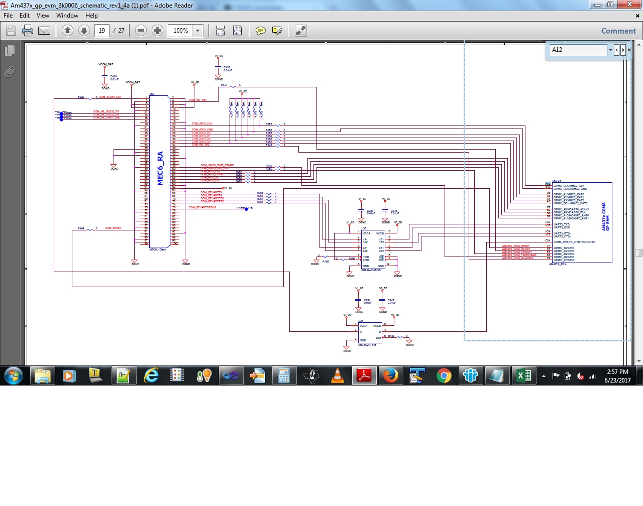
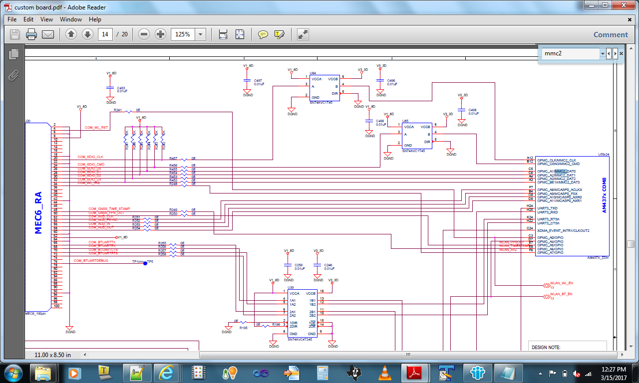
In EVM board, MMC2 clk, MMC2 CMD, MMC2 data lines are operating at 1.8V and it is directly connected to Wlink module. But in our Custom board, MMC2 Clk and  MMC2 Cmd are operating at 3.3V and MMC2 Data lines are operating at 1.8V. So we used Uni directional Level Translator for MMC2 Clk to connect to Wilink module and Bi directional Level translator to MMC2 Cmd to connect to Wilink Module. We directly connected data lines to wilink module. 

Now my doubt is Can we connect the same MMC with different voltages i.e Clk and Cmd with 3.3V and Data lines with 1.8V. If this is possible then please let me know what changes do i need to do in DTS file.

Please find the attached schematic changes

Iam requesting you to help me in solving this issue.
  • Hi,

    I suspect you may face timing issues by inserting level translators on only some of the MMC lines. Have you taken into account the delay through these? As for using the MMC interface at different voltage levels, you should use the Pinmux Tool to check if your combination is supported: processors.wiki.ti.com/.../TI_PinMux_Tool
  • Dear Biser,

        Thanks for the details. My doubt is Can we use different pins with different voltages of same MMC pheripheral? I got thsi doubt because when iam going through some of the forum links i found one interesting post which is exactly related to this. But i did not get any solution for that. The following is the link for that post

    http://e2e.ti.com/support/arm/sitara_arm/f/791/p/245394/858590?tisearch=e2e-sitesearch&keymatch=%20user:112102

    Refrefing to the above mail chains and refrening to the thread attached I found that, 
     
    SD_CAPA register can be configured to support 1.8V, 3.0V and 3.3V for MMC
    It says that if MMCHS 3: this field must be set to 5h i.e. 1.8V
    It says that if MMCHS 3: this field must be set to 7h i.e. 3.3V 
     
    On our Custom board SD_CLK and SD_CMD lines are toggling properly with 0V to 3.3V levels during initialization.
     
    Data lines gpmc_a1.mmc2_dat0, gpmc_a2.mmc2_dat1, gpmc_a2.mmc2_dat1, gpmc_a3.mmc2_dat2 are toggling from 0V to 1.8V.
     
    But whats confusing is that, the value of the SD_CAPA register needs to be either 1.8V or 3.3v at any point of time, 
     
    Is it possible to have mmc2 interface to operate having 2 different power domians, Can you please clarify.
     
    Thanks in advance. Your help is highly appreciated.
     
    With Regards
    Niranjana
  • Processor I/O pins operate at the voltage level to which the corresponding VDDSHVx for that pin is set.