Other Parts Discussed in Thread: OMAP-L138, SYSBIOS
There isn't much info in the upp peripheral datasheet for the c6657, about proper shtudown/stopping of these DMA transfers.
I need to stop and and start the UPP interface periodically in receive mode only. We have a ping-pong buffer (I'll call the lower half Buffer0 and the upper half Buffer1).
This is what happens:
1) Power up - UPID0 = 0x00000000
2) Currently the UPP behaves expected after reset (power-up) - End of window interrupt period is correct.
3) UPP transfer is stopped (UPID0 = the address of Buffer 0)
4) UPP transfer is started and the end of window interrupt period is correct
5) UPP transfer is stopped (UPID0 = the address of Buffer 1)
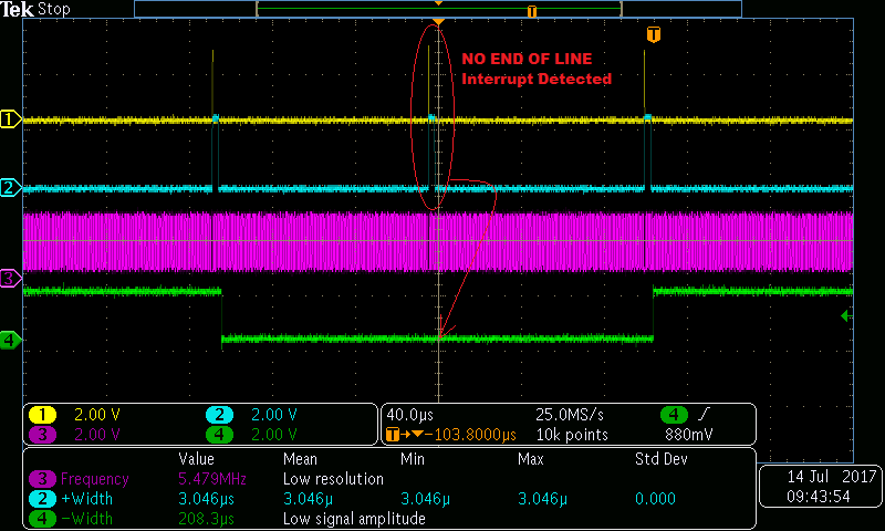
6) UPP transfer is started and the end of window interrupt is double.
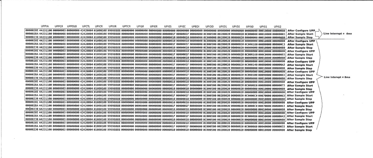
We are using the same routines to configure the UPP interface, line count, sine size...The only difference I see between the transfers is when I capture the Upp regsiters before and after each configuration sequence, the UPID0, UPID1, and UPID2 registers are different (ie they seem to have stale data from the previous transfer).
In our setup, the ISR programs the next DMA transfer, however when I want to stop the transfer it sets a flag, so when the ISR runs again, It does not program the next transfer. This should effectively let the upp dma run dry. It appears that I am still fighting with stale DMA configuration because of those register differences I"m seeing.
To Recap:
On power up the UPID0 register is 0x00000000
After I start and stop the transfer, the UPID0 register is the address of Buffer0
After I start and stop the transfer again, the UPID0 register is the address Buffer1
It seems like I need to get the UPID0 register to reset to 0x00000000,
Is there any way to reset the UPP's DMA so we can match our initial power on reset conditions?


