This thread has been locked.

If you have a related question, please click the "Ask a related question" button in the top right corner. The newly created question will be automatically linked to this question.

Linux/DRA750: GLSDK 3.02.00.03 ULPI interface sometimes registered failed

Part Number: DRA750

Tool/software: Linux

Hi expert,

1. I use GLSDK 3.02.00.03, sometimes error occur when dwc3 register ULPI interface.

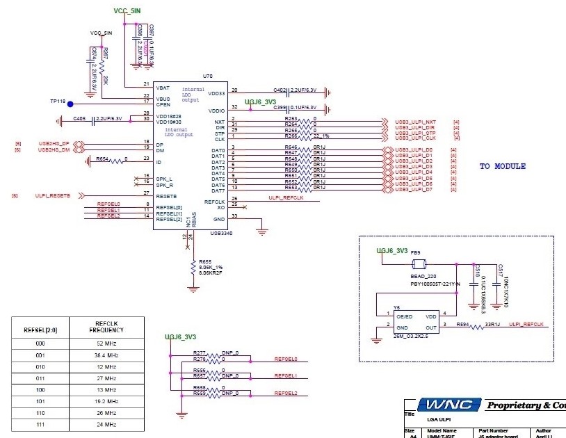
2. I use Microchip USB3340 as ULPI PHY and its reference clock set to 26 MHz (OUTPUT Mode, REFSEL[2:0] 110), it can let ULPI PHY to generate 60 MHz clock to CPU module.

3. Error message shows:

      [    5.597565] dwc3 48910000.usb: failed to register ULPI interface

4. I found the function ulpi_write(ulpi, ULPI_SCRATCH, 0xaa) in ulpi_register() error, that is, return value is -110 by dwc3_ulpi_busyloop(dwc) in dwc3_ulpi_write(), count=1000 and decrease to 0 and then timeout value ETIMEDOUT returned.

Could you please help to provide debug procedure.

Thank you.

BRs

Louis

  • Hi Louis,

    I have forwarded your question to USB experts.

    Regards,
    Yordan
  • Hi Yordan,
    Any response or I need to provide more information?
  • Hi Louis,

    Can you post or send us the schematic diagram between SoC and PHY?

    As far as I know ULPI was not tested after silicon release and ULPI pins remained only for backup. I think not much people have experience with ULPI.

    Regards,

    Stan

  • Hi Stan,

    The attached file is our schematic.

    BRs

    Louis

  • Louis

    Did you configure the pin-mux pad configuration for ULPI interfaces (ulpi_d0 to ulpi_d7, ulpi_stp, ulpi_clk, ulpi_dir, ulpi_nxt) appropriatly for USB3 or USB4 interface.

    Also, did you selected the ULPI external phy through USB_GUSB2PHYCFG (UTMI/ULPI) phy configuration register ?

    Regards
    Ravi
  • Hi Ravi,

    pin-mux pad configuration is no problem.

    How do I select the ULPI external phy through USB_GUSB2PHYCFG (UTMI/ULPI) phy configuration register ?
    Do I need to modify "./drivers/usb/dwc3/core.c" to achieve this? Or I can modify DTS ?
    BTW, this issue does not always happen, error rate around 1/170

    BRs
    Louis
  • Louis

    Yes, correct, you can set through DT as well, make sure the USB_GUSB2PHYCFG register are configured correctly , also review the pinmux & clock configuration is correct, clock on pin is toggling.
    Since the error rate is once in 170 iteration, during failure case whats happening with respect to ULPI signals (clock).

    Regards
    Ravi

  • Hi,
    Regarding the schematic, I've scrolled through microchip spec and through our TRM. I have the below questions/remarks.
    - You are in host mode, correct? (ID=0)
    - Looks like you need the 'VBUS power switch' to be present even in always-host mode and controlled by CPEN pin. I don't see it on your diagram
    - In host mode, you need Cvbus with at least 120 uF capacitance, see TABLE 8-2 in mchp spec
    - It's doubtful to me why is the 22-ohms for the ulpi clk? DAT pins can be as fast as CLK, but they are 0 ohms
    - (not critical) Rvbus you set it at the highest possible value (20k). It should be good , but I would select something in the middle 1-20k during tests

    Additionally, consider contacting microchip as most of the schematic you posted is related to the phy chip.
    And at last, as I already mentioned, ULPI interface doesn't have official TI support. It is there and has pins pinned out but it was not tested up to my knowledge. The device TRM is even more restrictive, it says 'do not use ulpi'...

    Regards,
    Stan
  • Hello Stan,

    Can you please tell us where in the TRM is the restriction mentioned ? I checked the TRM DRA75x_DRA74x_SR2.0_SR1.x_Public_TRM_vD, and could not find this info.

    Thanks and regards
    Karthik
    Harman Becker Automotive Systems GmbH
  • Karthik,
    I'm sorry, I was recalling the AM572x TRM where the USB is very similar. DRA75x doesn't have the restriction text.
    Still, I think ULPI is very rarely used with DRA75x, but nevertheless TRM and errata do not forbid ULPI use.

    Louis,
    One more to pay attention for : Check to which DRA75x balls the PHY is connected. And if these balls are powered 1.8V or 3.3V. See if PHY is at same voltage or tolerates the SoC-side voltage.

    Also please consider my comments in my previous post,.

    Regards,
    Stan

  • Hi Stan,

    1. Our hardware engineer response as below,

    - You are in host mode, correct? (ID=0)
    --> No concern, it connects to GND.
    - Looks like you need the 'VBUS power switch' to be present even in always-host mode and controlled by CPEN pin. I don't see it on your diagram
    --> No concern. It is a float pin.
    - In host mode, you need Cvbus with at least 120 uF capacitance, see TABLE 8-2 in mchp spec
    --> No concern. Power has other decoupling Caps.
    - It's doubtful to me why is the 22-ohms for the ulpi clk? DAT pins can be as fast as CLK, but they are 0 ohms
    --> Checking the document.
    - (not critical) Rvbus you set it at the highest possible value (20k). It should be good , but I would select something in the middle 1-20k during tests
    --> No concern. 20K Ohms follows datasheet requirement.

    BRs
    Louis
  • Hi Louis,

    The diagram doesn't show the connections down to the USB connector, therefore I don't have enough visibility...

    Can you post the diagram with the USB connector and signals? You can email me it f you wish.

    Thanks,

    Stan

  • Hi Louis,


    We are doing the same external PHY through ULPI interface.

    We can able to register dwc3 controller. but we can't bind generic PHY driver to dwc3 controller.

    Could you share DT setting for external phy (USB3340).?

    Regards,

    RAJ M