This thread has been locked.

If you have a related question, please click the "Ask a related question" button in the top right corner. The newly created question will be automatically linked to this question.

Linux/DRA725: Virtual and Manual I/O Timing Modes

Part Number: DRA725

Tool/software: Linux

Hi,

uboot version: 2016.05

 look the document  "DRA72x Infotainment Applications Processor Silicon Revision 2.0.pdf"
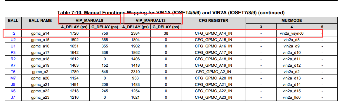
 

P203:

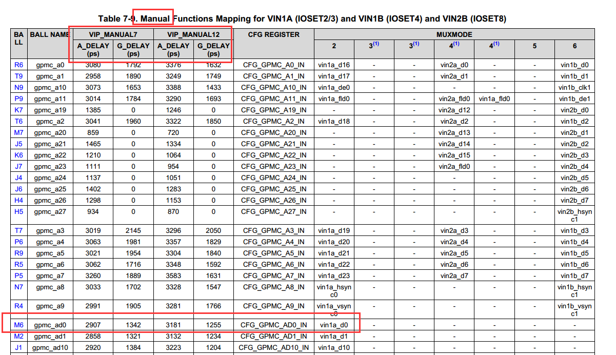
  the M6 pin is multiplex for vin1a_d0, so it must be set manual mode then set the A_DELAY and G_DELAY;

 but  I look the mux_data.h about config on the uboot , I find can't match.

file path: board/ti/dra7xx/mux_data.h


it set VIRTUAL_MODE12,  should it not set  manual mode?


Best regards,

Cesar.


  • Hello Cesar,

    I confirm it should be MANUAL_MODE12. We will report this bug to the SDK team. When in doubt, one should always follow the Data Manual as golden source.

    Thanks

    Alex

  • Hello Alex,

    how to do set delaying  on the mux_data.h file (board/ti/dra7xx) if it should be manual mode;

    example:

    the VIP_MAMUAL8  are  Rise-edge, the VIP_MAMUAL13 are  Fall-Edge

    them have different A_DELAY and G_DELAY, Which configuration should be selected or both of them have to be configured;


     because I look the configuration of mux_data.h are no difference between Rise-edge and Fall-Edge, it have one A_DELAY value and one G_DELAY only,   look:

            how to do config  the VIP_MAMUAL8 (Rise-edge), the VIP_MAMUAL13 (Fall-Edge)?

    Regards,

    Cesar.

  • Cesar,

    Well, which mode are you using the VIN interface? Fall or rise edge capture? Then you need to determine the IOSET you have these signals configured in. After you have determined these two, just follow the manual mode cross table and plug the numbers in, that's all.

    Thanks
    Alex
  • By the way, you can always try the Pad Configuration Tool (PCT). With that tool you will get to know these modes better and export values directly when you have the configuration in place int he GUI.

    Thanks
    Alex
  • Hi Alex,

    for example, I select the pin of ball name is mdio_d(U4), it's  multiplexed vin2a_d0, it belong to IOSET6


    1. so, the IOSET6 have exist both VIP_MANUAL3 and VIP_MANUAL5,so how to config?

    2. can you offer the PCT tool and how to use?


    Regards,

    Cesar.

  • Cesar,

    1. OK, so you have determined you are using IOSET6. Now, if you have the VIP configure in Rise-Edge Capture mode then use VIP_MANUAL3, if you have it configured in Fall-Edge Capture use VIP_MANUAL5.

    2. The PCT is currently NDA, contact your TI representative to obtain it. The PCT package contains a user manual and also there is an additional IODELAY app note (NDA also) that goes into a lot more details about iodelays and PCT tool configuration. 

    Hope it helps,

    Thanks

    Alex

  • Alex,
    thank you for your help.
    can you tell me where config the Capture mode.

    thanks,

    Cesar
  • Cesar,

    user4907611 said:
    can you tell me where config the Capture mode.

    Bare metal configuration is done in VIP_PORT_A register PIXCLK_EDGE_POLARITY bitfeld. How is confitured in the SDK I am not exactly sure, it looks like it should be in the ti_components\drivers\starterware_01_07_01_20\vpslib\hal\src\vpshal_vipPort.c driver.

    Thanks,

    Alex

  • Alex

    Thank you very mach, have a good time.

    Cesar.