This thread has been locked.

If you have a related question, please click the "Ask a related question" button in the top right corner. The newly created question will be automatically linked to this question.

CCS/TMS320VC5402: Why does the CLKOUT pin of the VC5402 output square wave?

Part Number: TMS320VC5402

Tool/software: Code Composer Studio

1、The /NMI and /BIO pins are all pulled up through the 10K ohm to the 3.3V;

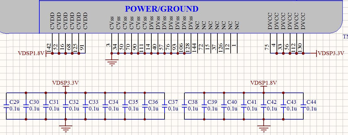
2、All CVDD pins voltages are normal to 1.8V,All DVDD pins voltages are normal to 3.3V,All the VSS pins are normally connected to the GND;

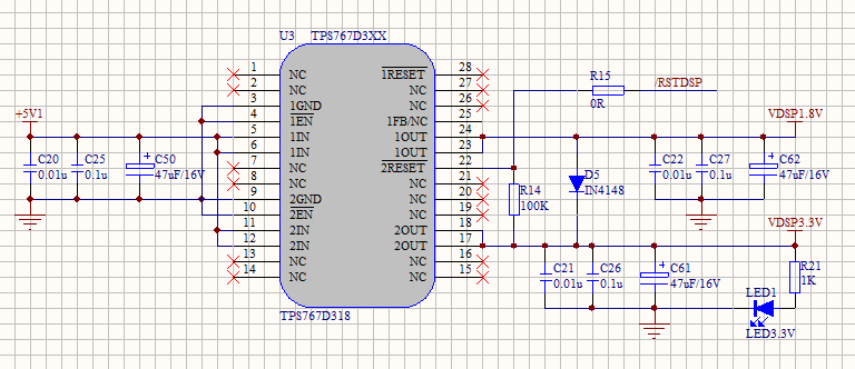
3、The system power IC is TPS767D318, and the RESET signal is provided for the VC5402;

4、My target board is only VC5402 and TPS767D318, and all other peripheral circuits are not welded;

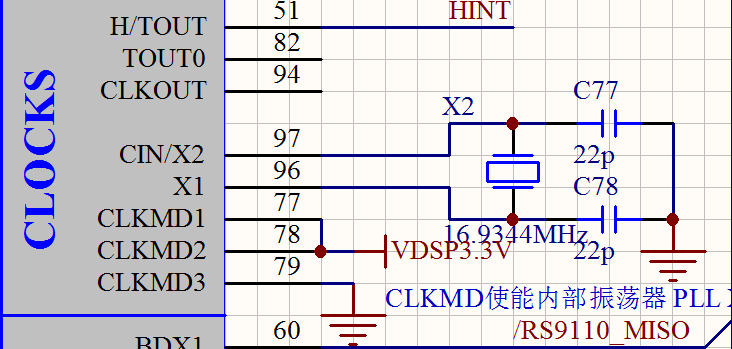
Part SCH follows:

The system power on, the x2 output sin wave,and the frequency is16.9344MHz,but the CLKOUT pin output square wave,and the frequency is 16.9344MHz, why?

To compare the test, I bought a SEED-MS5402 DSK board, CLKOUT output waveform, normal sine wave。

I've tested four TMS320VC5402 chips in all, and the problems are the same。

  • I've forwarded your query to the hardware design team. Their feedback should be posted here.

    BR
    Tsvetolin Shulev
  • Thank you, I wait for your reply, this problem has been bothering me for three weeks.

  • Hello!As of now, I have not received your reply to my question。
  • Hello and sorry for the delay.

    It is normal for the waveform at the crystal to be sinusoidal and the waveform for the CLKOUT pin to be a square wave.

    Are you saying the CLKOUT pin on the SEED-MS5402 DSK board outputs a sine wave? Perhaps CLKOUT could appear as a sine wave if there a low pass filter connected the CLKOUT pin on the PCB, or if the frequency of the CLKOUT pin is much higher than 16.9344MHz, or if the probe used is bandwidth limited.

    The crystal is part of an internal oscillator circuit that generates a square wave clock for the system to use. Usually this square wave feeds a PLL that generates a faster square wave system clock, which is fed to the system. The crystal is the mechanical resonator portion of that oscillator circuit, which can be modeled with a Capacitor, Inductor, and Resistor circuit. The output of the crystal is an analog voltage that scales with the distortion of the quartz in the presence of an electric field. It resonates at a specific frequency and will look like a sinusoidal waveform when probed.

    The CLKOUT pin is a CMOS output buffer that drives high for half the cycle and drives low for the other half. It requires some rise and fall time (2ns for this device) to transition from high to low and low to high, but otherwise it looks like a square wave. If the period of the CLKOUT square wave decreases enough (frequency increases), the square wave may begin to look like a triangle wave and then a sinusoid (as the period consists of just rise and fall time - less than 4ns).

    For this device, the frequency of the CLKOUT pin depends on the crystal input frequency and the CLKMD pins latched after reset, which specify the PLL multiplication factor. Your schematics indicate that the PLL is running in PLL x1 mode. So it is logical that the CLKOUT pin frequency matches the frequency of the crystal on X1/X2 (16.9344 MHz).

    Is there another question that I missed? I dont see a problem here.

    Refer to these pages in the datasheet (http://www.ti.com/lit/ds/symlink/tms320vc5402.pdf)

    * switching characteristics of the CLKOUT pin on page 39 of the datasheet

    * clock generator on page 22 of datasheet

    More details on oscillators with external crystals (and the CLR model) can be found here...

    http://www.ti.com/lit/an/sloa060/sloa060.pdf

    http://www.ti.com/lit/an/snaa065a/snaa065a.pdf

    Hope this helps,
    Mark