This thread has been locked.

If you have a related question, please click the "Ask a related question" button in the top right corner. The newly created question will be automatically linked to this question.

Divide by zero is legal in C64x+?

Other Parts Discussed in Thread: TMS320DM6437

Hi,all
I want to know what BIOS will do when an exception occurs.
So I do some experiments. In a very simple program a integer
is divided by zero, but nothing happens. Then a pointer is assigned
an address in the resersed range in the memory map, and nothing
happens again.

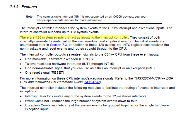
In the document TMS320C64x+ DSP Megamodule Reference Guide
There is a table System Event Mapping, and the table contains no such
event. I can't understand it.

When an internal exception occurs, what will happen in C64x+?
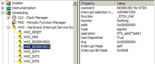
Are ISRs provided with BIOS/DSP? What does ISRs do?

Best Regards
Jogging

  • The things you've mentioned so far are not exceptions.  A list of exceptions can be found in the 64x+ CPU Reference Guide.

    Section 6.5.1 of spru732h said:

    Causes of internal exceptions:
    · Fetch error
    – Program memory fetch error (privilege, parity, etc.)
    · Single input from L1P returned with data indicates error
    – Two branches taken in same execute packet
    – Branch to middle of 32-bit instruction in header-based fetch packet
    – Branch to header
    · Illegal fetch packets
    – Reserved fetch packet header
    · Illegal opcode
    – Specified set of reserved opcodes
    – Header not in word 7
    · Privilege violation
    – Access to restricted control register
    – Attempt to execute restricted instruction
    · Register write conflicts
    · Loop buffer exceptions (SPLOOP, SPKERNEL)
    – Unit conflicts
    – Missed (but required) stall
    – Attempt to enter early-exit in reload while draining
    – Unexpected SPKERNEL
    – Write to ILC or RILC in prohibited timing window
    – Multicycle NOP prior to SPKERNEL or SPKERNELR instruction

    Try branching into your bss section and I imagine you'll hit an exception pretty fast.  BIOS has added handlers for the exceptions.  When it catches one it will log the exception in the System Log and then sit in a spin loop doing nothing.  In CCS go to DSP/BIOS -> Message Log and select "Execution graph details" (or something similar I'm not in front of it) and it will show some of the details such as the kind of exception as well as the address of the exception.

    I think the exceptions have been one of the most useful new features of 64x+ compared to the older 64x.  In the older architecture the chip would go off into the weeds if you did something bad in your code and the result would just be an emulator crash.  Now it can actually catch many of these things and point you to the root cause.

    Brad

  • Thanks, Brad
            Your information is very helpful.
             I try many times but fail to generate a exception. When  the exception occurs and handlers sit in
    a spin loop loop doing nothing, what does DSP/BIOS think?  DSP/BIOS considers that this ISR is finished
    and will move on to schedule other thread?
             In the document SPRU871J-August 2008, on the page 158
    it says:
    The interrupt controller outputs seventeen signals to the C64x+ CPU from these event inputs:
    · One maskable, hardware exception (EXCEP)
    · Twelve maskable hardware interrupts (INT4 through INT15)
    · One non-maskable signal that
    · One reset signal (RESET)

    There are 15 event inputs, but the interrupt controller outputs seventeen signals. I don't
    understand signals here. How does it generate seventeen signals from 15 event inputs?

    Best Regards
    Jogging

  • There are 16 hardware interrupts but four of them are reserved (INT0 is RESET, INT1 is NMI, INT2/3 are reserved for RTDX). I am not sure why this document does not include the two reserved interrupts for RTDX, but there are indeed two more to round out the full 17 outputs.

    If you don't mind please submit this feedback by clicking the "Submit Documentation Feedback" at the bottom of every page of that document.

  • Jogging Song said:

    Thanks, Brad
            Your information is very helpful.
             I try many times but fail to generate a exception. When  the exception occurs and handlers sit in
    a spin loop loop doing nothing, what does DSP/BIOS think?  DSP/BIOS considers that this ISR is finished
    and will move on to schedule other thread?

    BIOS considers this a catastrophic event so it logs the event to the System Message Log and then sits in a spin loop.  You can plug in additional handlers if you desire.  Generally this is more useful for development because it's generally a result of a hardware issue or else a software bug (i.e. uninitialized pointer causing CPU to jump into the weeds).

    Jogging Song said:

             In the document SPRU871J-August 2008, on the page 158
    it says:
    The interrupt controller outputs seventeen signals to the C64x+ CPU from these event inputs:
    · One maskable, hardware exception (EXCEP)
    · Twelve maskable hardware interrupts (INT4 through INT15)
    · One non-maskable signal that
    · One reset signal (RESET)

    There are 15 event inputs, but the interrupt controller outputs seventeen signals. I don't
    understand signals here. How does it generate seventeen signals from 15 event inputs?

    Best Regards
    Jogging

    Where did you come up with 15 inputs?  It says in that same paragraph that there are 128 inputs.  I'm attaching a screenshot.


  • Thanks

    Tim, I search the document and find RTDX doesn't appear in it. But in the document of processors such as
    SPRS345D TMS320DM6437. It seems that two interrupts of rtdx belong to 128 system events. I have
    submitted this question.

    Brad, You are right. There are 128 system events and the interrupt selector route them to any of
    twelve CPU interrupt inputs. I just add the events in the following lists together.

    Best Regards
    Jogging

  • Brad,

    I think he meant the 15 system interrupts to the CPU listed in his earlier post (12 maskable, reset, nmi, exception). Quoted from p158 of SPRU871J:

    The interrupt controller outputs seventeen signals to the C64x+ CPU from these event inputs:
    · One maskable, hardware exception (EXCEP)
    · Twelve maskable hardware interrupts (INT4 through INT15)
    · One non-maskable signal that
    · One reset signal (RESET)
    As you can see it only lists 15 signals, not the full 17 (it's missing the two reserved for RTDX).

  • Hi, Tim

    In my opinion, maybe at first two interrupts for RTDX are output directly like NMI.
    But later these interrupts are put into the 128 system events and output through
    INT4-INT15. If you search RTDX in the document SPRS345D TMS320DM6437, you will find
    EMU_RTDXRX and EMU_RTDXTX on the page 200. So the other two interrupts are not
    related to RTDX.

    Best Regards
    Jogging

  • I'm not exactly sure what their purpose is, but there are two hardware interrupts reserved specifically for some RTDX functionality not related to the mappable TX/RX interrupts. See the attached screen capture from a BIOS configuration file. These two events are not described in the document, but they are definitely there and are not maskable.