Because of the holidays, TI E2E™ design support forum responses will be delayed from Dec. 25 through Jan. 2. Thank you for your patience.

This thread has been locked.

If you have a related question, please click the "Ask a related question" button in the top right corner. The newly created question will be automatically linked to this question.

TMDSLCDK6748: Sine Wave Generator using mcaspPlayBk.c

Part Number: TMDSLCDK6748

Hi,

I'm trying to send a sine wave to the codec using the mcaspPlayBk.c demo code. The generated sine wave looks like this in Code Composer:

It's encoded using 32-bit signed integers and interleaved into the transmit buffer wiht LSB first:

Then I'm sending the data to the transmit buffer to the MCASP controller. 

            //reassemble into 2-channel buffer
            interleave2(tempBufferInt, AUDIO_BUF_SIZE/8, (void *)txBufPtr[lastSentTxBuf]);
/*
            memcpy((void *)txBufPtr[lastSentTxBuf],
                   tempBuffer,
                   AUDIO_BUF_SIZE);
                 */

            /*
            ** Send the buffer by setting the DMA params accordingly.
            ** Here the buffer to send and number of samples are passed as
            ** parameters. This is important, if only transmit section
            ** is to be used.
            */
            BufferTxDMAActivate(lastSentTxBuf, NUM_SAMPLES_PER_AUDIO_BUF,
                                (unsigned short)parToSend,
                                (unsigned short)parToLink);

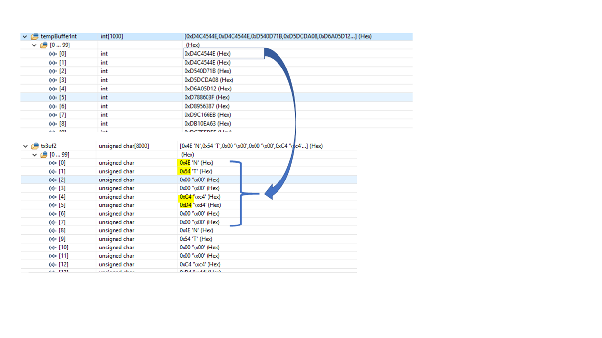
The problem is the output is scrambled in the transmit buffer txBuf:

I think the samples from the sine wave aren't being sent to the codec correctly. 

thank you,

Scott

  • Hi,

    I've notified the RTOS team. Feedback will be posted here.

    Best Regards,
    Yordan
  • The data in the McASP examples in starterware is using I2S mode, which means the data in the audio TX/RX buffers will have left and right channel data which is then given to the codec which is expecting the data in that format for transmission. Instead of generating the the data on the DSP can you generate the data using host sosftware like Audiacity and then input the signal from host into the line in and check to see if the data loops back on the line out. 

    If you are generating the data on the DSP then, you will need to generate the data in left right channel format and have it adjusted to the codec gain and quantization before sending it to the codec.

    Regards,

    Rahul

  • Hi Rahul,

    I changed the input signal to be an external signal from Audacity. If I feed the audio thru using the out-of-box code, it works. 

    But if I change the data in any way (say, divide-by-two), then the output is noise. So I'm trying to determine the format that the codec expects the data to be in.

    I tried decoding the data as an interlaced 2-channel 32-bit signed integer. So to decode it, I'm taking 2 non-adjacent 2-byte blocks and concatenating them into a single 32-bit integer. Is this correct?

    I think this must be incorrect because when I interleave the 32-bit integer back into the original 2-channel byte-based buffer, the signal is not reconstructed.

    thank you,

    Scott

  • Hi,

    If anyone has any suggestion on how to resolve this issue, please advise.

    thank you.

  • I changed the input signal to be an external signal from Audacity. If I feed the audio thru using the out-of-box code, it works.

    But if I change the data in any way (say, divide-by-two), then the output is noise. So I'm trying to determine the format that the codec expects the data to be in.

    I tried decoding the data as an interlaced 2-channel 32-bit signed integer. So to decode it, I'm taking 2 non-adjacent 2-byte blocks and concatenating them into a single 32-bit integer. Is this correct?

    I think this must be incorrect because when I interleave the 32-bit integer back into the original 2-channel byte-based buffer, the signal is not reconstructed.
  • Scott,

    From what Rahul explained, your data is either supposed to be a series of signed 16-bit pairs or signed 32-bit pairs depending on how you have the McASP and codec configured. The fact that you are talking about bytes and non-adjacent blocks makes me think you are looking at the data wrong.

    With the code that is working, can you halt the processor and look at the Txbuf in CCS and send a screen shot? Format the data as 32-bit signed TI-style. Ideally, the data would be close to a single tone so it is easier to read by eye, but whatever you have, send that screenshot with a description of what it sounded like.

    Another thing you could try with your original sinewave data is to transmit an exact copy of tempBufferInt or copy tempBufferInt exactly into txBuf2 without the 0's inserted in the middle. If one channel sounds like a sinewave and the other sounds like noise, then your data is 16-bit pairs; if both channels sound like a sinewave that is double the expected frequency, then your data is 32-bit pairs.

    Regards,
    RandyP
  • Hi RandyP,

    I'm decoding the data from the ADC/codec as 32-bit signed pairs. This gives the sine wave shown above (thereby reconstructing the input analog signal).

    I talk about bytes because the data is transmitted in bytes (correct me if I'm wrong). I don't see how discussing bytes can be avoided, unless it's transmitted along a larger data bus.

    I have halted the CPU and sent screen shots of txBuf above. It is 32-bit signed TI-style. The input signal is a single tone sine wave.

    thank you,

    Scott

  • Here is a snapshot of rxBuf. If you compare it to txBuf (above), they do not look the same. 

    Also, I meant to say that I talk about bytes becasue rxBuf and txBuf are of type char. But since the samples are 32-bit signed integer, I have to write a function to convert char to signed int. Please let me know if this sounds incorrect.

    thank you,

    Scott

  • I've also tried to show the waveforms that I'm seeing along the way. I hope it's visible. It shows that I have an analog input, then captured in rxBuf, then a temp buf to verify the waveform, then send it back to the codec. I showed it as 2 separate codecs even though it's one. 

  • Hi RandyP,

    Have you been able to look at the screen shots you asked for?

    thank you,

    Scott

  • Scott,

    You are displaying your waveforms as 16-bit unsigned, not 32-bit signed. You are using the failing data, not the passing case. The passing data would probably be more useful as a Memory Browser display and not a graph, but in some ways the graph is more useful.

    The data is obviously interleaved of two 16-bit numbers. And you are somehow corrupting the data since it looks completely different from the input to rxBuf to the output of txBuf. That is something you should be able to debug through even with this data, before redoing this with the passing data which would be more helpful after the debug.

    Regards,
    RandyP
  • scott said:
    Also, I meant to say that I talk about bytes becasue rxBuf and txBuf are of type char. But since the samples are 32-bit signed integer, I have to write a function to convert char to signed int. Please let me know if this sounds incorrect.

    Yes, this sounds incorrect. Data type seems to be a problem in the display and in the buffer data. Casting can be confusing, so mixing definitions adds to it.

    Regards,
    RandyP