This thread has been locked.

If you have a related question, please click the "Ask a related question" button in the top right corner. The newly created question will be automatically linked to this question.

Linux/AM3354: CAN transmit problem

Part Number: AM3354

Tool/software: Linux

Hi:

i'm using AM3354 for a while and we had many different products designed based on this MCU.

we used CAN communication a lot and most of the product it seems fine.But still there are times that newly designly board run into strange CAN transmition problems.BSP stays the same as always.

right now we have a product of the hardware schematic version 1.0. The CAN is working fine.

I'm attaching the schematic here.

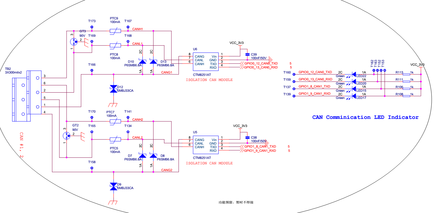
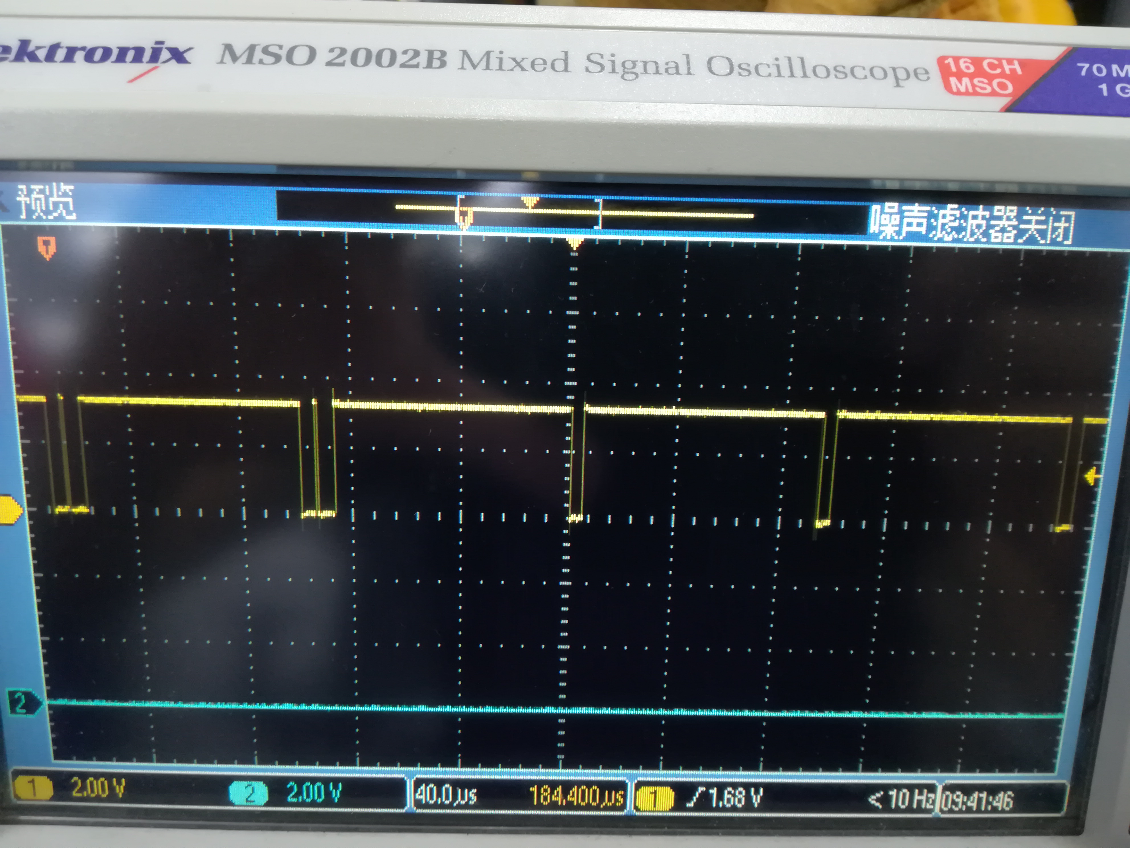
and when we tried to transmit a CAN frame. The wave looks ok.we are not connecting the CAN to somewhere else so the CAN bus is disconnected from any other node.That's why you can see the constant retrying by CAN controller hardware within MCU.

The command lines are:

 canconfig can0 bitrate 50000 ctrlmode triple-sampling on

canconfig can0 start

cansend can0 -i 0x10 0x51

we are sending the data of value 0x51.

and the wave look like this:

Now.Here is the weird part.

On the same product but the next version of hardware which is 1.1. The CAN transmit strange wave no matter what i wanted to send.And the receiver of course can't get anything right.

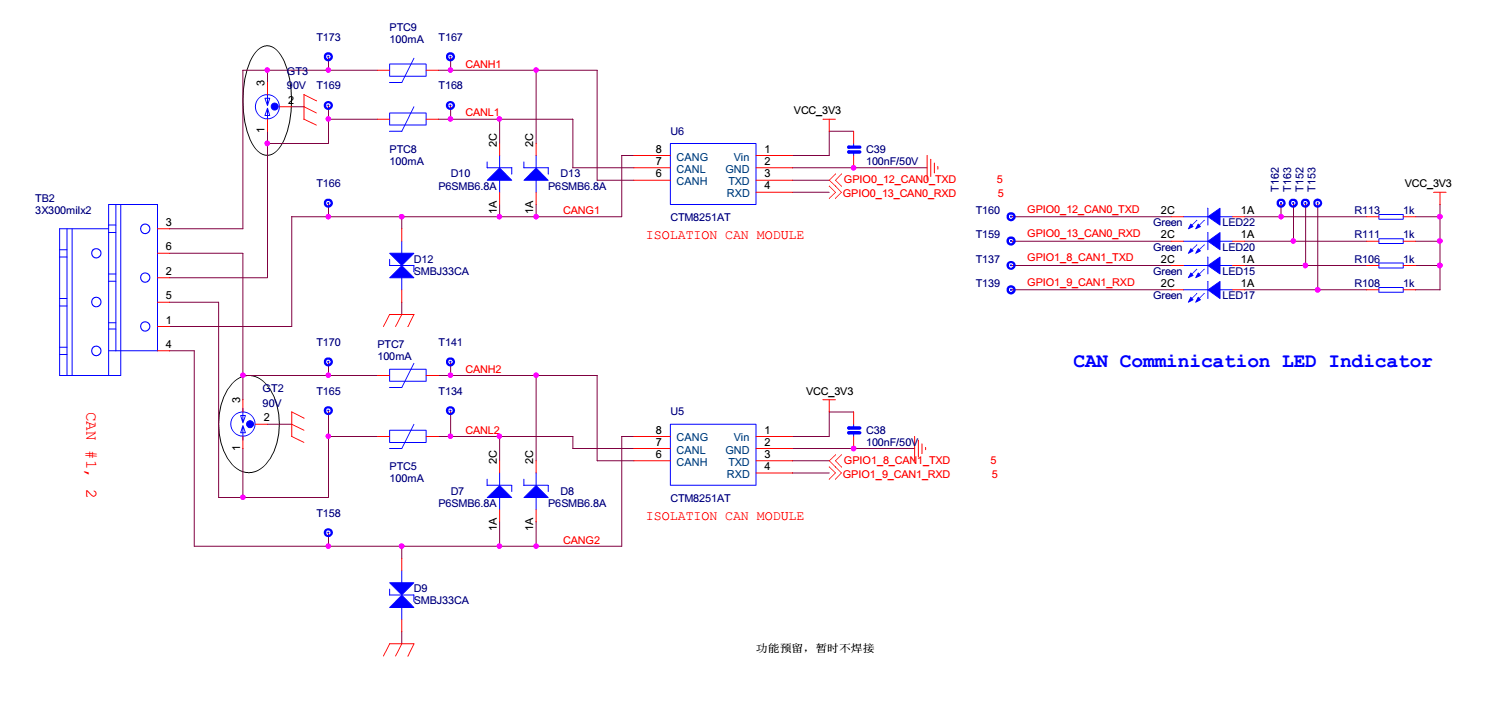
I'm attaching the schematic of 1.1 hardware here.But in actual you can see it's the same as 1.0 hardware.

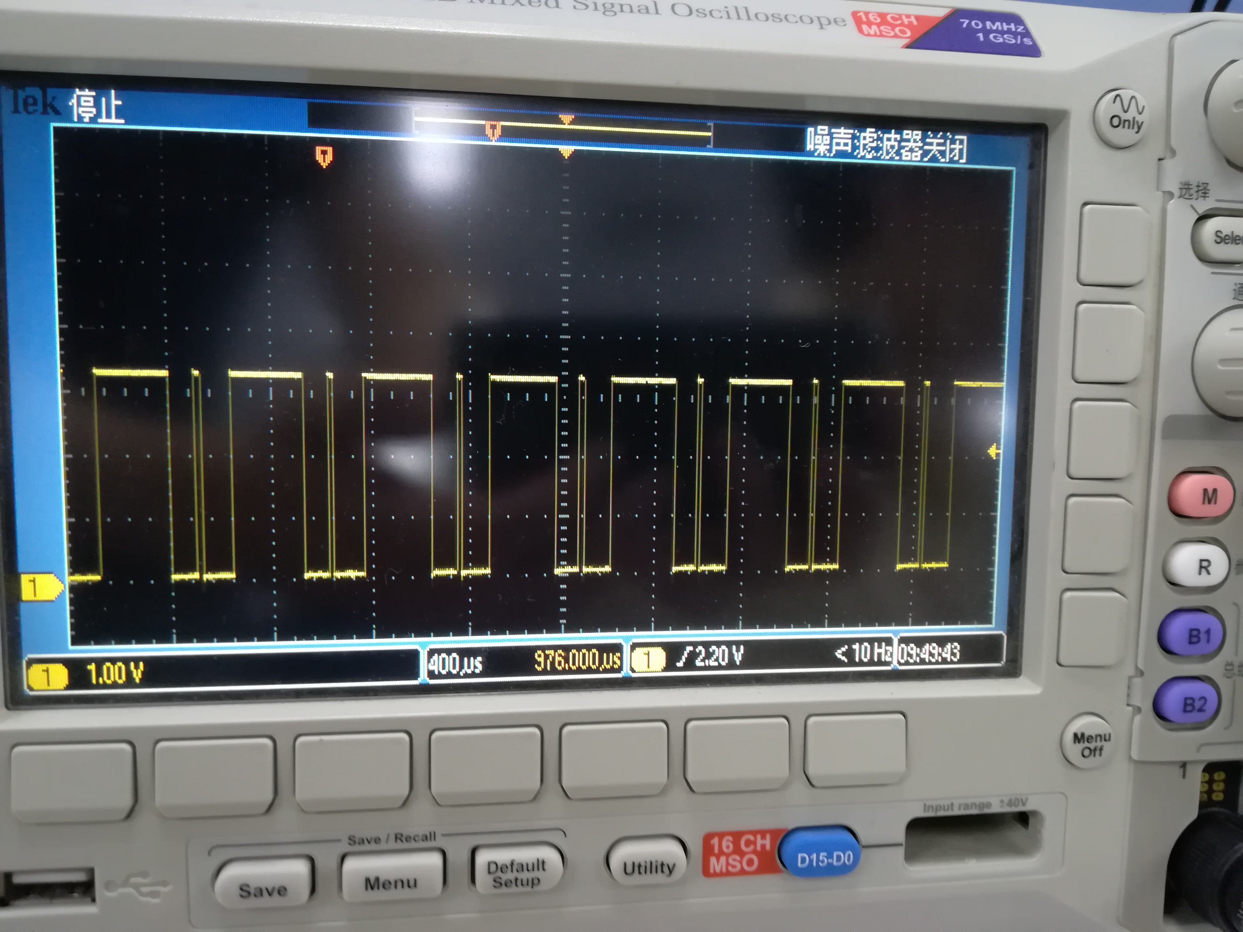
  and when we tried to transmit a CAN frame. The wave looks strange.we are not connecting the CAN to somewhere else so the CAN bus is disconnected from any other node.That's why you can see the constant retrying by CAN controller hardware within MCU.

The command lines are also the same:

 canconfig can0 bitrate 50000 ctrlmode triple-sampling on

canconfig can0 start

cansend can0 -i 0x10 0x51

we are sending the data of value 0x51.

and the bad wave look like this:

The strange part is the BSP is 100% not changed between hardware 1.0 and 1.1

and at least the schematic of 1.0 and 1.1 regarding CAN functionality is also the same.

Can you guys help me?

thanks a lot in advance.

yandong

  • The CAN experts have been notified. They will respond here.

    Please post what Linux version you are using? Where are you measuring the waveform? At processor side or at CAN side?
  • hi Biser:
    On this product i'm using kernel 3.2.0 extracted from sdk 06.00.00.00.
    And i'm measuring the waveform directly at the processor side pins.Which is the node named "GPIO0_12_CAN0_TXD" on the schematic i attached.

    thank you.


    yandong
  • can anyone help me please?

  • Sorry about the delay. I have escalated the request. Meanwhile can you check if both boards are running on the same OSC0 frequency?
  • Hi,

    One test to start off with is what does the waveform look like at different bit rates. Could you please attach a waveform using the 500000 bit rate? Also please try 1000000 as well. Is there a reason that 50K was selected?

    Best Regards,
    Schuyler
  • Hi Biser

         Our boards are composed of the core board and the base board.

         the MCU , OSC0 , nand flash , DDR are on the core board.

         both board are using the same core board.

        So that part of OSC0 and OSC1 stays the same.

    thanks

  • Hi Schuyler:

        the reason 50k is used is because that the frequence we really use in our actual application in the field.

        So.with the same command:

        cansend can0 -i 0x10 0x51

        a test with 500k speed:

    the can controller sent the waveform above and then went to bus off state.the can txd no longer send any waveform.unlike 50k.

    2nd test with 1M speed:

    this time the can controller sent the waveform above and then went to bus off state.the can txd no longer send any waveform.also unlike 50k.

    thank you!

    yandong

  • I also tried to run the BSP from 03.02.00.05 SDK on the board with linux 4.4.32.
    The problem is the same.
    It's unlikely a BSP caused issue.
  • Hi,

    Thanks for trying a later SDK to see if the issue is still present. That was going to be something that I was going to suggest as a means of isolating the problem.

    When a bus off condition is detected it could mean something external to the SOC usually the path between the SOC the transceivers should be reviewed to make sure the termination resistors are in place. Another thing to consider is the cable being used is not introducing un-expected impedances. Is the device on the other end the same one used for testing with a 1.0 board? Does the 1.0 board still work with the other CAN device?

    Regards,
    Schuyler
  • Thank you for the suggestion Schuyler.

    we did not connect the 1.1 or 1.0 board to any other CAN nodes or boards..

    the CAN bus is open(no external cable attached) and we did not have termination resistors installed.Because we thought in this case we are not connecting to anywhere else.So normally in this case termination resistors is not needed yet.

    However the finding is once we install the 120ohm termination resistors.The waveform look ok.

    we have other products running on CAN as well.And normally it's up to the customer if the termination resistors is to be installed or not.Depending on the distance of communication.

    That's what i'm told by our hardware engineer.

    If we have a fixed termination resistors on board like 120ohm.Then the customer may or may not be aware of the fixed 120ohm termination resistors and then install yet another one by himself.Which makes two termination resistors.I don't know in that case this will be a problem?

    thank you so much for the help!

    yandong

  • Hi,

    I am glad that the suggestion worked for you. I will have to ask a HW team member to supply an answer here concerning what happens if the line terminated twice.

    Best Regards,
    Schuyler
  • Thank you Schuyler!

    Please inform me once you have any suggestions!

  • Hi Yandong,

    The CAN standard requires that the connecting cable be terminated at both ends with 120ohm resistors. This is an exert from the TI App note Controller Area Network Physical Layer Requirements. Transmitting into an unterminated cable will not provide valid signalling. 

    The High-Speed ISO 11898 Standard specifications are given for a maximum signaling rate of 1 Mbps with a bus length of 40 m and a maximum of 30 nodes. It also recommends a maximum un-terminated stub length of 0.3 m. The cable is specified to be a shielded or unshielded twisted-pair with a 120-Ω characteristic impedance (ZO). The Standard defines a single line of twisted-pair cable with the network topology as shown in Figure 6. It is terminated at both ends with 120-Ω resistors, which match the characteristic impedance of the line to prevent signal reflections. According to ISO 11898, placing RL on a node should be avoided since the bus lines lose termination if the node is disconnected from the bus.

    Regards, Bill

  • Thank you Bill!

    that explains crystal clear.