This thread has been locked.

If you have a related question, please click the "Ask a related question" button in the top right corner. The newly created question will be automatically linked to this question.

AM3352: LCD read latency in LIDD mode

Part Number: AM3352

Hello!

I am interesting about the LCD read latencies. 

When I read the LCD data in the LIDD mode (using StarterWare) with edma (or without, it will be the same situation), each reading operating latency is about 200 ns. If I need to read 16 bytes I have to wait 16/2 * 200 = 1600 ns.

I find the read latencies table for PRU, where LCD read latency is equal to 38*5 = 190 ns: 

Also I find the L3 topology (spruh73k, p.1468, Figure 10-1), the PRU and the edma (TPTC) both located at the L3F area. 

Am I correctly understand, that it is not possible to read data faster, using LCD, LIDD mode? Or I can read the LCD data faster using edma?

  • Hi,

    Check section 7.10.1 in the AM335x Datasheet Rev. J. You will notice that the minimum cycle time of LCD_MEMORY_CLK is 23.7ns plus additional timing requirements. Also, each read cycle takes several LCD_MEMORY_CLK periods to complete. I suggest you first check your external LIDD timings and try to tune them for best performance.
  • Thank you for your reply!

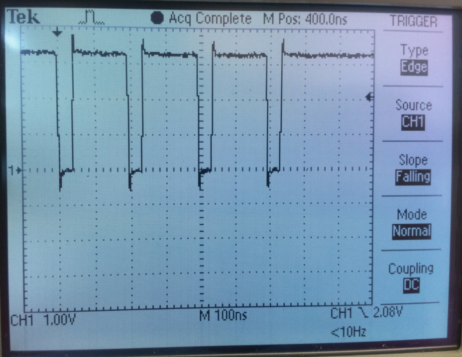
    I tune the LIDD timings for write and read operations (LIDD_CS0_CONF and LIDD_CS1_CONF registers). Write operations work properly. One read operation work properly too, but between two read operations became the latency. I attach the screenshot of the CS signal during two read operations.

    It can be seen 200 ns delay between two operations. 

    I had the same situation when I wanted to read data from GPIO. I can write fast, but read more slowly. The delay between two read operations using LCD or GPIO interfaces is equal to the latencies at the PRU LATENCUES TABLE.

  • Alex, the LIDD controller is optimized for write operations in order to facilitate LCD updates. I'm not sure you'll be able to get highly optimized reads across the LCD interface in LIDD mode. Have you tried setting up the MMU+cache for that memory region?

    Also, what is your configuration when you setup the EDMA? You may need to adjust your element size (ACNT, BCNT) to optimize for the interface width.

    Regards,
    James
  • JJD, thank you for your reply!

    I enable the MMU and cache using the StarterWare functions "CacheEnable(CACHE_ALL)" and "MMUConfigAndEnable". "MMUConfigAndEnable" function enable memory region that called "Device memory region" with Start_address = 0x4400_0000 and num_sections = 960. The LCD is included to this memory region.

    My EDMA settings are:

    srcAddr = 0x4830e018;//LIDD_CS0_DATA

    destAddr = ptr // my buffer

    aCnt = 2; // one write operation to LCD is 2 bytes

    bCnt = 4; // sent 4x2 = 8 bytes

    cCnt = 1;

    srcBIdx = 0;

    srcCIdx = 0;

    destBIdx = 2;

    destCIdx = 0;

    such EDMA transfer oscillogram is (lcd_ac_bias_en – LIDD_CS0 signal):

    As I understand there are no ways to get highly optimized reads?

  • Alex, i think this will be the best performance you can get on the interface with read transactions. I don't think read performance was a high priority on this interface, and most of the focus was ensuring write performance (as is evidenced by the DMA feature within the controller). I would say typically reads are not needed since most applications will either just rewrite the whole display buffer or write the certain locations which need updating.
    Not sure what information you are reading from the display, but you might consider caching the information if it is not volatile and only modified by the processor.

    James
  • JJD, thank for your reply. I am using the LCD at the LIDD mode as a parallel interface to connect with non-display device (for example the linux has special drivers for ethernet-on-GPMC, I want to use the LCD the same way).