This thread has been locked.

If you have a related question, please click the "Ask a related question" button in the top right corner. The newly created question will be automatically linked to this question.

CCS/TMS320C5545: programming connector issue

Part Number: TMS320C5545


Tool/software: Code Composer Studio

Hi 

I'm using C5545 in own system.

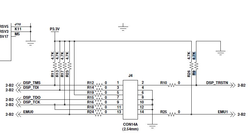
This is my part of schematic

Is this correct? I'm using XDS200

  • We're looking into this.

    Best Regards,
    Yordan
  • Hi minkyo seo,

    The JTAG pinout looks correct, and you have sufficent pull-ups on TMS, TDI, TCK, EMU0, EMU1.

    The pull-down on TRSTN is required to prevent the device from entering into a test mode after reset.

    An additional pull-up on TDO would provide power savings of around 500uA when no JTAG pod is attached, but there is no functional impact without it. The TDO signal is always an output, but the IO buffer on this device and other C5505/15/35 devices has the input buffer enabled. Avoid floating inputs for power savings.

    Ensure your XDS200 has the includes 14-pin adapter to mate with this header.
    This one comes wiht 3 adapters: www.ti.com/.../TMDSEMU200-U

    A good reference for JTAG board level design is www.ti.com/.../spru589a.pdf

    Your schematic lines up with Figure 3-1. 14-Pin Target Header Pin Dimensions in this document.

    Ensure JTAG signals map to the female header on the JTAG emulator. Consider which side of the board the header will be populated to avoid getting it mirrored (if through-hole).

    Hope this helps,
    Mark