


Part Number: AM5728
Tool/software: Linux
Hi,
I have a TMDSEVM572X AM572x Evaluation Module. The schematic files are : TI_AM572XEVM_REV_A3a.pdf, ti_am572x_evm_lm_a2a.pdf, AM572X_GP_EVM_CAMERA_C1.pdf. The SDK that i am using is
ti-processor-sdk-linux-am57xx-evm-04.00.00.04 based on ubuntu16.04.
Because we're going to shoot moving objects, we use a new camera with sensor mt9v032. What needs to be explained is that we keep the new camera's interface the same with TI's OV10635 camera module,so it can be connected to P9 of the EVM successfully. Then i want to write the new driver for my new camera following the mt9t11x demo . That means modifing the file am57xx-evm-common-cam-mt9t111.dtsi(/opt/ti-processor-sdk-linux-am57xx-evm-04.00.00.04/board-support/linux-4.9.28+gitAUTOINC+eed43d1050-geed43d1050/arch/arm/boot/dts/) and mt9t11x.c (/opt/ti-processor-sdk-linux-am57xx-evm-04.00.00.04/board-support/linux-4.9.28+gitAUTOINC+eed43d1050-geed43d1050/drivers/media/i2c) . My question is : Is my idea right ? If i am wrong , then what should i do ? which files need to be modified ?
Still, i have some other questions:
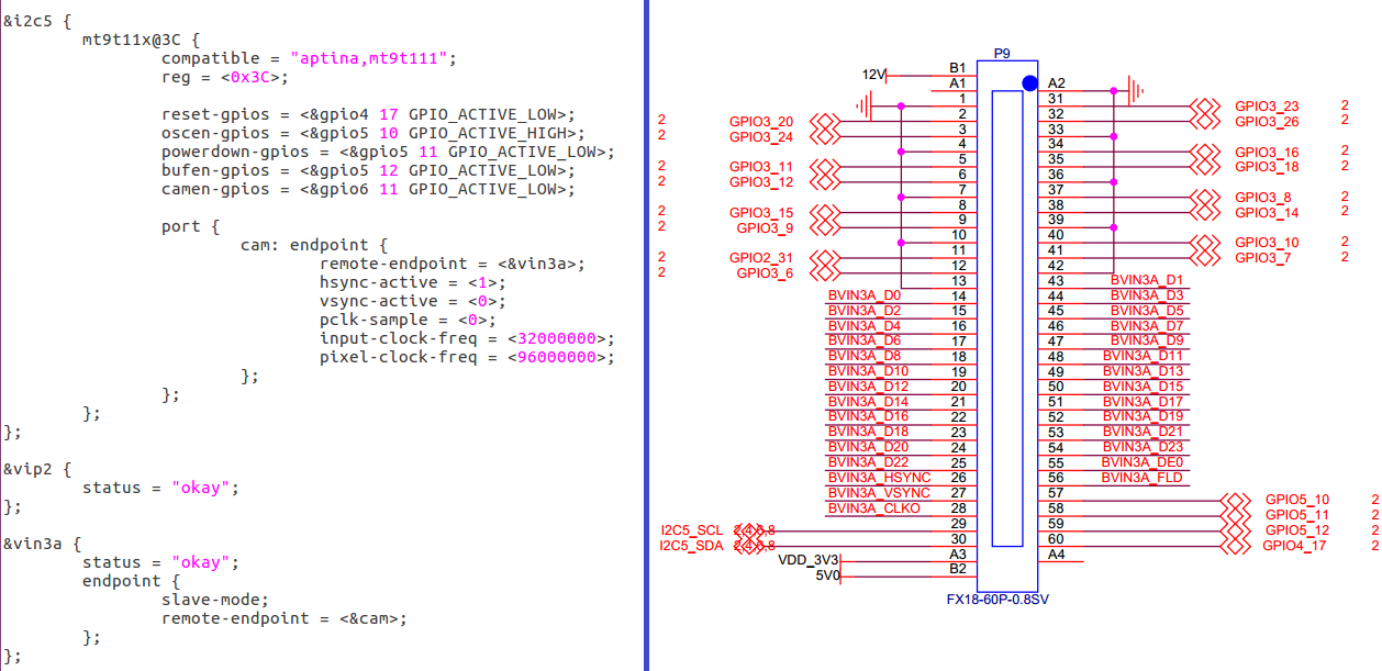
1. If my idea mentioned above is right . A dedicated clock oscillator is provided for my camera module, it works at 27MHz and provids 27 MHz clocks to the sensor mt9v032. Then the camera's pixel clk (pclk) is 27MHz too, which is connected to the BVIN3A_CLKO of P9 (pin num : 28). Do i have to modify the "pixel-clock-freq=<96000000>" to "pixel-clock-freq=<27000000>" in am57xx-evm-common-cam-mt9t111.dtsi? what does the "input-clock-freq= <32000000>" means ? when the linux kernel gets the information of "pixel-clock-freq = <96000000>" and "input-clock-freq=<32000000>" , what kind of work will it do? whether TI has a detailed document on the description of the device tree?
2.After reading the mt9t11x.c file, my understanding is that the mt9t11x just acts as a subdev of the V4L2 framework.Does this means when we want to add a new camera driver ,we just have to add a new subdev to the V4L2 framework? If the ansower is yes, then: As far as I know , the complete V4L2 framework consists of video_device, v4l2_device and v4l2_subdev . Is it because TI has implemented the work of video_device and v4l2_device according to am5728 platform , so we just have to complete the v4l2_subdev subsection?
3. Is the video capture framework for TI only based on V4L2 or anything else? For example, the soc_camera framework? I want to read this part of the code in detail, but I don't know what documents to look at, and whether TI has a detailed document on the description of this piece?
Expecting someone to give a solution.


