This thread has been locked.

If you have a related question, please click the "Ask a related question" button in the top right corner. The newly created question will be automatically linked to this question.

AM3351: SD boot time too long

Part Number: AM3351

Hi,

customer uses AM3351 in this configuration (for production test):

Bootmode 0b11100 (sysboot[4:0]). So boot sequence should be MMC1 -> MMC0 -> UART0 ->USB0.

They connect an empty 4GB eMMC card at  MMC1 and at MMC0 is SD card slot /adapted via testadapter to SD card.

SD card at MMC0 contains a bootable image.

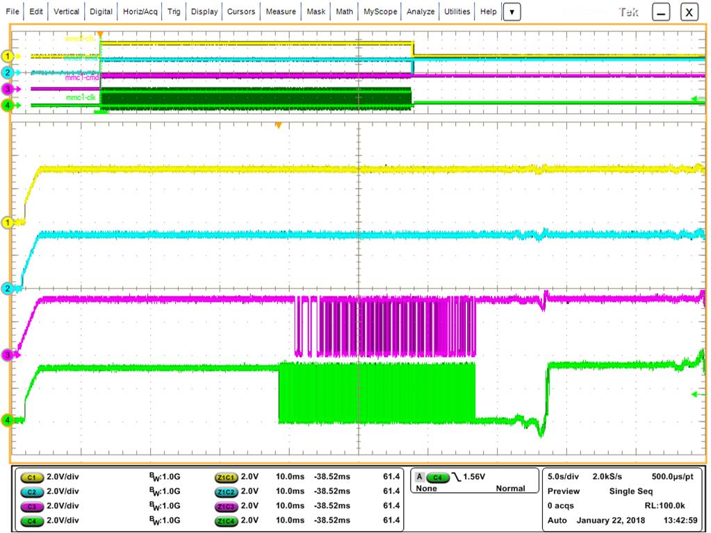
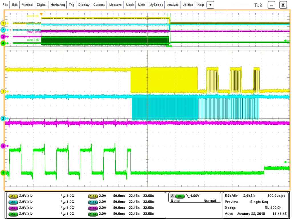
As expected they see, that MMC1 is selected and then MMC0 (with bootable image), but time between change form 0 ->1 take about 20 seconds!

Question: whats is reason for long timespan until selecting MMC0 ? This makes testing time in endproduction longer as expected.

  • Hi,

    DJ-NG said:
    time between change form 0 ->1 take about 20 seconds!

    Can you clarify this? Are you sure that MMC0 is read on first attempt? Do you see any "CCC..." characters on debug terminal?

    DJ-NG said:
    MMC0 is SD card slot /adapted via testadapter to SD card.

    Please provide more details about this too.

  • Hi Biser,

    here is detailed answer from customer:

    yes it is around 20 seconds to change from 0 -> 1. (see screenshot below [yellow=mmc0-clk, lightblue=mmc0-cmd, purple=mmc1-cmd, green=mmc1-clk)

    Detail mmc1:

    Detail mmc0:

    C-characters will be printed 8 times each 20 seconds.


    To connect the mmc0 interface to an external SD-socket including card will be used at the EMS side as a part of testing procedure. The “test SD card” will include as booting image the test application. This application will perform a functional test on the assembled pcb. Here in R&D lab we use the pcb mounted SD socket and a SD card directly.


    The eMMC is for example a 4GB TOSHIBA device (THGBMDG5D1LBAIL) in PSLc mode. That means half of capacity, 2GB instead of 4GB, but higher reliability.

  • Something is very wrong if you see the "C" characters. This means that MMC1 and MMC0 boot have both failed, and UART boot has been reached. I suggest you start by checking your SYSBOOT voltage levels at reset release time.
  • Hi Biser,

    seems, that issue was not described completely:

    Sorry but you misunderstood something. For testing the bootprocedure described below, we have of course a working testapplication image on a SD card. In case the SD card is plugged into the socket, there are no “C” characters printed.
    But then there is a delay from 1st bootsource to 2nd bootsource by 20 seconds.

    If I remove the SD card (just for testing) then unfortunately there is no bootable image in the system. Then of course the ROM loader jumps to 1st bootsource (mmc1) forward to 2nd bootsource(mmc0) then 3rd bootsource (uart0) and last 4th bootsource (usb0).
    While being at 3rd bootsource  8 time C character is printed. This I did just as a test to verify your request.

  • Hi Biser,

    Any news ?
    Customer is waiting for an answer.
  • Dirk, what does the "empty" eMMC contain? The fact that the MMC1 clock continues to toggle throughout the 20 seconds makes me believe that the ROM is attempting to read from it, which means that the ROM thinks there is a valid image in the eMMC. Then finally it times out and moves on to the next boot source.

    Regards,
    James
  • James,

    • Empty means the device i staken out oft he tray soldered tot he pcb and then startet testing without any data on it.

    • Toogle frequency is something below 100Hz.

    • The eMMC is not formatted put put in pSLC mode

    • The SD card is FAT formatted an contains the test application as a boot image

    Do you think issue has tpo deal with this:

    The eMMC is for example a 4GB TOSHIBA device (THGBMDG5D1LBAIL) in PSLc mode. That means half of capacity, 2GB instead of 4GB, but higher reliability.

    Pls come back if you need more information!

  • The toggle frequency of 100Hz doesn't make sense either. Do you mean that the MMC_CLK during the 20 sec in eMMC boot is toggling at 100Hz? It should start out at 400KHz, then switch to 12MHz.
    Is there any way they can connect JTAG during that 20sec and report the where the program counter is?

    Regards,
    James
  • Hi James,

    The MMC1_CLK starts with a frequency of 100kHz. With this frequency there is some kind of traffic on the MMC1 port. After certain amount of bytes it seems like the interface switches to a different mode what ends up in a stop of data transfer on the CMD line and lowering the frequency to something around 100Hz. In this state the MMC1 port stays nearly 20 seconds before the next boot source is switched to.

    JTAG interface can be connected to see where the program counter is.

    To make my statement meaningful the measurements will be done again but with a better granularity.
  • James,

    can you help ?
  • Can you give us a snapshot of the PC, the ARM core registers (R0-15), MMC controller registers, and PER PLL registers during the 20 seconds the MMC_CLK is at 100Hz.

    Regards,

    James

  • Hi everybody, by delay condition the programm counter is located to 0x00024192. Additional content you ca get from attached screen shots.

  • Can you also provide the other information James requested?

    Steve K.
  • Could you please specify the adresses for the requested register.
  • Another point is that the eMMC is switched to pSLC mode. What means that the MMC controller sees 2GB instead of 4GB. May that have impact to the behavior?
  • The register is CM_CLKSEL_DPLL_PERIPH at 0x44e0049c.

    How do you switch the eMMC to pSLC mode?
  • We've switched to pSLC Mode during verification of internal test application like described by JEDEC. Because this procedure is OTP there is no way back right now.

    The register content i can provide tomorrow. Can you please additinally specifiy the MMC controller register which are of interessed. I guess it's not all of them.
  • The mmc1 registers. Let's start with 0x481D8124, 0x481D812C, 0x481D8224, 0x481D822C, 0x481D8230.

    Steve K.
  • The registers content is

    0x44E0049C:      0x0403C018

    0x481D8124:      0x00000000

    0x481D812C:      0x00000600

    0x481D8224:      0x01F70006

    0x481D822C:      0x000E0407

    0x481D8230:      0x20108000

  • Gerald, can you give us one more register at 0x481D8240 (SD_CAPA).

    We believe what is happening is that you are getting a data timeout (DTO) because the eMMC is not responding as the ROM expects. One way to check this is to put a HW breakpoint at address 0x24196, and see what the value of R3. This will determine the error that breaks out of the loop after 20 seconds.
    The error may be a result of pSLC mode as you suspect. We are not too familiar with these types of eMMC, so I'm not sure if there is a different command structure that either a) the eMMC does not recognize the commands from the ROM or b) the ROM is not recognizing the responses from the eMMC. Is there any way you can get a board with the eMMC that is not in this mode?

    Regards,
    James

  • Hi James,

    the content of SD_CAPA (0x481D8240) is 0x02E10080.

    Regarding the content of R3 from our point of view it looks like the rom-code is waiting for a value != 0 in MMC1 SDSTAT register.

    The content of R3 at HW breakpoint 0x24196 is 0x20008000

    Here is the complete picture

  • I'm interested in your eMMC extcsd. Are you using a TI file system? If so you can use the mmc command to dump the extcsd with
    mmc extcsd read /dev/mmcblk1

    I'd like to see the output.

    Steve K.
  • It does look like you are getting a DTO (data timeout) plus a bad address error. Based on the value in SYSCTL.DTO and CLKD, the data timeout does equate to about 20sec (MMC functional clock at that point is 96MHz/16=6Mhz, which is a 166ns cycle time, and 166ns *2^27= 22sec)

    We are suspecting the DTO is due to the pSLC mode. At the point of failure, the ROM is sending CMD8 and it doesn't seem to be getting an expected response, thus it waits 20sec and finally times out. Can you test a board without a eMMC in pSLC mode?

    Regards,
    James
  • There is no file system on eMMC (MMC1)! The device is completely clear. Just the pSLC mode is set by pretesting
  • May this behaviour arise because the eMMC is downgraded from a 4GB device to a 2GB device due to setting pSLC mode and (according to SPRUH73) the MMC1 port expects 4GB or greater (Chapter 26.1.7.5.2)
  • It is possible that this could be related to the pSLC device "looking" like a 2GB eMMC, but this may not be the ultimate reason.  Is it possible to access or flash the eMMC device when booting from SD card?  This will help eliminate many potential h/w issue getting in the way.

    Regards,

    James

  • The eMMC is accessable when the ~20 secondes delay is past. Then the boot image on SD card (mmc0) is used and our test application works a expected.

    Are you able to adjust let's say a beagle bone black board to reproduce the described behaviour.
  • Gerald, can you confirm the part number of the eMMC? Earlier in the post it was identified as Toshiba THGBMDG5D1LBAIL, but I'm seeing this on the web as an end of life memory. I'm not able to get any sample of the 4GB version.

    Regards,
    james
  • The current part number we use is THGBMDG5D1BAIL. As far as i know THOSIBA will change the controller fab what ends up in a change on part numbering to THGBMNG5D1BAIL.
  • James has some eMMC on order. We'll continue debug when they come in.

    Steve K.
  • Today i got new assembled boards and started testing.

    1st test: pcb as delivered from EMS including 4Gbyte eMMC boot mode (boot[4:0] = 0b11000)
    -> behaviour like expected switching boot sources

    2nd test: pcb as delivered from EMS including 4Gbyte eMMC adjusted boot mode (boot[4:0] = 0b11100)
    -> behaviour switching boot mode interruppted for ~20 seconds

    3rd test: pcb as delivered from EMS including 4Gbyte eMMC adjusted boot mode (boot[4:0] = 0b11100) and set eMMC to enhanced (pSLC) mode.
    -> behaviour switching boot mode interruppted for ~ 20seconds

    4th test: new dut with 8Gbyte eMMC and boot mode (boot[4:0] = 0b11000)
    -> behaviour like expected switching boot sources

    5th test: new dut with 8Gbyte eMMC and boot mode (boot[4:0] = 11100)
    -> behaviour switching boot mode interruppted for ~20 seconds

    6th test: new dut with 8Gbyte eMMC and boot mode (boot[4:0] = 11100) and set eMMC to enhanced (pSLC) mode.
    -> behaviour switching boot mode interruppted for ~20 seconds

    From these six tests to me it does not look like there is any relation to eMMC size or enhanced mode is active or not regarding the ~20 seconds interruped boot procedure. Even testing acorss different eMMC devices and vendors does not have impact here.
  • Gerald, thanks, this is a good step. I think now it seems there is something in the hardware on the interface that is causing the ROM to result in a data timeout. Can you send the portion of the schematic with the eMMC (or send via the local FAE if it is sensitive info)

    Thanks,
    james
  • Hi, you will get the schematic vialocal FAE DJ-NG.
  • Coming back to the shematic i figured out that the eMMC in my schematic is connected to GPMC_AD[8:15]. These pins are not specified as boot pins for MMC1 by the rom bootloader.

    MMC1 bootpins the rom bootloader defines GPMC_AD[0:3] for eMMC_D[0:3] and GPMC_nCS[1:2] for eMMC_CMD/CLK. In my schematic to the pins GPMC_AD[0:3] a nVSRAM is connected.

    So i can imagine that the rom bootloader is requesting an boot-image but there will be no activity on the data pins what may be confusing for the bootloader.
  • Just for a test i've connected the eMMC via air wires like requested by rom bootloader. The result is that the bootsources are stepped through without any interrupt or delay. I think that the issue is solved.
  • Am i right?? Could you please explain a bit?