This thread has been locked.

If you have a related question, please click the "Ask a related question" button in the top right corner. The newly created question will be automatically linked to this question.

TMDSIDK437X: Pinmux in PRU training lab

Part Number: TMDSIDK437X

Hello,

I have been trying to work through the PRU Training Hands on Lab (found here: ) using the TI AM437x Industrial Development Kit, as opposed to the Beaglebone Black, and have come across a few questions.  In Lab 1, the R30 register is being written to, which controls the PRU GPO as far as I can tell, so as to toggle the on-board LEDs.  However, when I compile and try to run the code on the IDK, the LEDs do nothing.  I believe the source of this problem is that the board's Pinmux file has Mode 0 selected for the LEDs, where the pins control various LCD and CAM1 signals (seen here under the LEDs section: ).  My question is then, can I change these Pinmux settings to their GPO equivalent mode (Mode 5) or are they "locked" in Mode 0 to perform a specific function on the development kit?  If I can change them, do I do this in the Pinmux Application or in Code Composer Studio?  Any information would be greatly appreciated.

Thank you very much,

Broydon Stufko

  • Hello Broydon,

    I am taking a look and will get back to you tomorrow.
    Nick
  • Hello Broydon,

    Pins LCD_PCLK & LCD_VSYNC (LED0), and CAM1_WEN & CAM1_DATA2 (LED1) are not connected to anything else on the board, so they are just for LED control (from the AM437x IDK schematic). The other two signals going to LED 0 and 1 might also be free, I didn't have time to look into their connection to the expansion header.

    Changing to Mode 5 looks like the correct approach. If you're building in Linux, I like to make small tweaks to the pinmuxing directly. Example flow below. 

    user:~/ti-processor-sdk-linux-am437x-evm-04.02.00.09/board-support$ grep -r 'cam1_data2'

    tells us that pin is set in u-boot, and again in linux for am437x-gp-evm. It is not set in am437x-idk-evm, so we will need to add lines instead of tweaking them. Modify the ti-processor-sdk-linux-am437x-evm-04.02.00.09/board-support/linux-4.9.59+gitAUTOINC+a75d8e9305-ga75d8e9305/arch/arm/boot/dts/am437x-idk-evm.dts file to match, but change from MUX_MODE0 to MUX_MODE5.

    If that process doesn't work for you, let me know.

    Regards, 

    Nick

  • Nick,

    Thank you for the reply.  I am fairly new to the Embedded world and will give this a shot.  I believe it has answered my questions.

    Thanks,

    Broydon

  • Hello Broydon,

    Here's a more "official" process for making tweaks to the pinmux settings:

    1) find pinmux info in schematic/datasheet:

    cam1_wen doesn't mux to the PRU outputs

    cam1_data2 muxes to pr0_pru1_gpo10 with muxmode 4

    dss_pclk(LCD_PCLK in schematic) muxes to pr0_pru1_gpo8 with muxmode 5

    dss_vsync(LCD_VSYNC in schematic) muxes to pr0_pru1_gpo6 with muxmode 5

    Let's say you decide to use dss_pclk and cam1_data2 (pr0_pru1_gp8 and pr0_pru1_gp10).

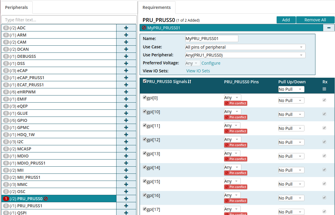
    2) Use the TI pinmux tool to generate the device tree modifications you need. Check out the wiki for more information about the tool. Go to version 4 of the pinmux tool, open an am437x, and select peripheral PRU_PRUSS0:

    By default all the signals are selected (hence the Red mark next to MyPRU_PRUSS01, because multiple signals are getting routed to the same pin). Uncheck the box next to "PRU_PRUSS0 Signals", and you should get a green check by MyPRU_PRUSS01 indicating that there are no pinmux conflicts.

    Check the box next to gpo[8] and gpo[10]. Select the proper output pins (A22 and AD21 respectively). Change the pull settings as needed.

    Check out the Output > Generated Files section of the PinMux tool. The code you'll want to insert into ti-processor-sdk-linux-am437x-evm-04.02.00.09/board-support/linux-4.9.59+gitAUTOINC+a75d8e9305-ga75d8e9305/arch/arm/boot/dts/am437x-idk-evm.dts is in the devicetree.txt file:

    mypru_pruss01_pins_default: mypru_pruss01_pins_default {
    	pinctrl-single,pins = <
    		0xe8 ( PIN_OUTPUT | MUX_MODE5 ) /* (A22) dss_pclk.pr0_pru1_gpo[8] */
    		0x1f0 ( PIN_OUTPUT | MUX_MODE4 ) /* (AD21) cam1_data2.pr0_pru1_gpo[10] */
    	>;
    };

    Regards, 

    Nick