This thread has been locked.

If you have a related question, please click the "Ask a related question" button in the top right corner. The newly created question will be automatically linked to this question.

66AK2H14: 66AK2H14

Part Number: 66AK2H14

Hi,

66AK2H14 is interfaced to Altera MAX10 series CPLD through EMIF16 interface.

EMIF16 is configured to Select Strobe Mode.We have to perform CPLD read/write through EMIF16.

In EMIF16 user guide spruza.pdf.
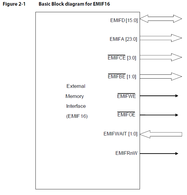
We have connected CPLD to CE2.

Q1 : how to configure EMIFD[15:0] , EMIFA [23:0] , EMIFCE2 , EMIFBE[1:0] , EMIFWE , EMIFOE as we don't have any specific register in 66AK2H14.

Regards,

Mahima Shanbag

  • The team is notified. They will post their feedback directly here.

    BR
    Tsvetolin Shulev
  • Hi,

    For K2H, the EVM has a NAND flash connected to the EMIF interface. The schematic is here: http://www.ti.com/tool/EVMK2H, there is link to the manufacture website to see how the NAND pins are connected.

    For the software side, there NAND writer is pdk_k2hk_4_0_x\packages\ti\boot\writer\nand\src, this calls into platform function to configure the EMIF interface: pdk_k2hk_4_0_x\packages\ti\platform\evmk2h\platform_lib\src

    Regards, Eric
  • Hi Eric,
    Thank you for your suggestion.
    In pdk_k2hk_4_0_x\packages\ti\boot\writer\nand\src we have seperate registers CSL_GpmcRegs for NAND to write the address,data and command.
    Likewise where I have to write the address and control signals like EMIFCE2 , EMIFBE[1:0] , EMIFWE , EMIFOE for CPLD.
    Q1: Is there any registers to configure the address and control signals.

    Q2: In 66AK2H14 data sheet -> device memory map (page no-78) EMIF16 CE2 is mapped to 38000000-3BFFFFFF.We have connected CPLD to CE2. My doubt is whether I have to write data that has to be transmitted through EMIF16 to this address ?

    Regards,
    Mahima Shanbag
  • Hi Mahima,

    Details on configuring the EMIF16 are found in the External Memory Interface (EMIF16) for KeyStone Devices User's Guide (Rev. A). Did you have questions on the contents of that document?

    Regards, Bill

  • Hi Bill,

    yeah... I have doubt in configuring the  EMIFD[15:0] , EMIFA [23:0] , EMIFCE2 , EMIFBE[1:0] , EMIFWE , EMIFOE as per the block diagram

    Q1: Is there any registers to configure the address and control signals.

    Q2: In 66AK2H14 data sheet -> device memory map (page no-78) EMIF16 CE2 is mapped to 38000000-3BFFFFFF.We have connected CPLD to CE2. My doubt is whether I have to write data that has to be transmitted through EMIF16 to this address ?

    Regards,

    Mahima Shanbag

  • Hi Mahima,

    The EMIF16 is pretty flexible when connecting to asynchronous devices. The block diagram shown represents the possible signals that can be generated by the interface but the async device you are connecting may not need them all. You need to determine what control signals are needed and program their behavior. Since you are interfacing with a CPLD, you have flexibility at both ends and can customize the interface at the CPLD to work with the EMIF16. I suggest you keep that interface simple and use a 16bit data bus with a simple CE, WE and RE interface.

    Q1: The address lines are carried though from the lower address bits of the memory map with the shift described in section 2-5 of the EMIF16 users guide. Remember that A23 is used as the least significant address line for x16bit interfaces. The control signals are programmed using the Async 2 Config Register (A2CR). Details on this register are found in the users guide. It will allow you configure the setup, cycle and hold times for the control signals to define the period when the data bus is active.

    Q2: The addresses range you have shown is directly mapped to the external memory device. The upper portion of the address is internal only and will not be carried through to the EMIF address lines but are needed to access that particular CE inside the K2H.

    Regards, Bill