Other Parts Discussed in Thread: OMAPL138, OMAP-L137, OMAP-L138, CSD
Tool/software: TI-RTOS
I'm using a customized board with C6748. A 16Gb eMMC device (MTFC16GAKAECN-2M) is used for external storage.
I try to use the eMMC driver example in pdk_omapl138_1_0_3, but face some problems.
So there are 2 example applications, non-DMA and DMA version. The only difference with or without the MMCSD_EDMA_ENABLED definition.
There is a main.c and a main_emmc.c file in the \ti\pdk_omapl138_1_0_3\packages\ti\drv\mmcsd\test\src
So I use the main_emmc.c.
And I replace all "#if !defined(SOC_OMAPL137)" with "#if !defined (SOC_OMAPL137)|| !defined (SOC_OMAPL138)"
The nonDMA version can work normally, all test pass.(polling mode and interrupt mode both succeed)
But the DMA version seems cannot work normally.(polling mode and interrupt mode both failed)
For the DMA version, I set
After building and run, when the program runs into "retVal = MMCSD_write(handle, &tx[0], blockNum, TESTSECTORS);", the program stuck at it.
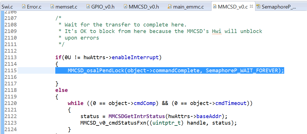
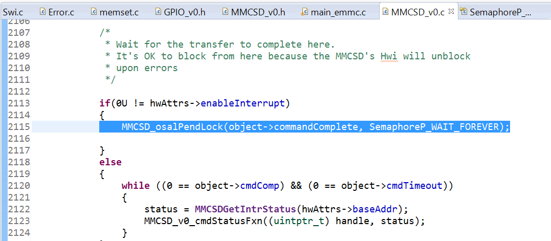
I stepped into the program, and find the program stuck at here: The 1st call of MMCSD_osalPendLock() in the MMCSD_v0.c.
Attatched are the nonDMA version and DMA version projects I use.
Q1: What's wrong with the DMA version?
Q2:Or can TI provide me a DMA version with Interrupt enabled that suit for C6748+eMMC, which can work normally?
Q3: With the nonDMA(polling or interrupt) version. If I takes 2 MMCSD_write() one after another without delay. The program will stuck at the MMCSD_write(). A delay(10) between the 2 MMCSD_write() will make it work.
Is there mechanism that guarantee the MMCSD is ready before another access is taken out? Such as a ready flag? So that the nonDMA version can be used freely.
Thank you.
MMCSD_lcdkOMAPL138_c674xTestProject.zip
MMCSD_lcdkOMAPL138_DMA_c674xTestProject.zip
/**
 *  \file   main.c
 *
 *  \brief  Test application main file. The test application demonstrates
 *          raw data write & read on a MMCSD device.
 *
 */

/*
 * Copyright (C) 2014-2017 Texas Instruments Incorporated - http://www.ti.com/
 *
 * Redistribution and use in source and binary forms, with or without
 * modification, are permitted provided that the following conditions
 * are met:
 *
 * Redistributions of source code must retain the above copyright
 * notice, this list of conditions and the following disclaimer.
 *
 * Redistributions in binary form must reproduce the above copyright
 * notice, this list of conditions and the following disclaimer in the
 * documentation and/or other materials provided with the
 * distribution.
 *
 * Neither the name of Texas Instruments Incorporated nor the names of
 * its contributors may be used to endorse or promote products derived
 * from this software without specific prior written permission.
 *
 * THIS SOFTWARE IS PROVIDED BY THE COPYRIGHT HOLDERS AND CONTRIBUTORS
 * "AS IS" AND ANY EXPRESS OR IMPLIED WARRANTIES, INCLUDING, BUT NOT
 * LIMITED TO, THE IMPLIED WARRANTIES OF MERCHANTABILITY AND FITNESS FOR
 * A PARTICULAR PURPOSE ARE DISCLAIMED. IN NO EVENT SHALL THE COPYRIGHT
 * OWNER OR CONTRIBUTORS BE LIABLE FOR ANY DIRECT, INDIRECT, INCIDENTAL,
 * SPECIAL, EXEMPLARY, OR CONSEQUENTIAL DAMAGES (INCLUDING, BUT NOT
 * LIMITED TO, PROCUREMENT OF SUBSTITUTE GOODS OR SERVICES; LOSS OF USE,
 * DATA, OR PROFITS; OR BUSINESS INTERRUPTION) HOWEVER CAUSED AND ON ANY
 * THEORY OF LIABILITY, WHETHER IN CONTRACT, STRICT LIABILITY, OR TORT
 * (INCLUDING NEGLIGENCE OR OTHERWISE) ARISING IN ANY WAY OUT OF THE USE
 * OF THIS SOFTWARE, EVEN IF ADVISED OF THE POSSIBILITY OF SUCH DAMAGE.
 *
 */


/* XDCtools Header files */
#include <xdc/std.h>
#include <xdc/cfg/global.h>
#include <xdc/runtime/System.h>
#include <stdio.h>
#include <ti/sysbios/knl/Task.h>

/* BIOS Header files */
#include <ti/sysbios/BIOS.h>
#ifdef MMCSD_EDMA_ENABLED
#include <ti/sdo/edma3/drv/edma3_drv.h>
#include <ti/sdo/edma3/rm/edma3_rm.h>
#include <ti/sdo/edma3/drv/sample/bios6_edma3_drv_sample.h>
#endif
#include <xdc/runtime/Error.h>

/* TI-RTOS Header files */
#include <ti/csl/cslr_device.h>
#include "MMCSD_log.h"
#include <ti/drv/mmcsd/MMCSD.h>
#include <ti/drv/mmcsd/soc/MMCSD_soc.h>

#include <ti/board/board.h>

/* Example/Board Header files */
#if defined (evmAM437x)
#include <ti/starterware/include/hw/am437x.h>
#include <ti/starterware/board/am43xx/am43xx_pinmux.h>
#endif

#include <ti/drv/gpio/GPIO.h>
#include <ti/drv/gpio/soc/GPIO_soc.h>

#include <ti/drv/gpio/soc/GPIO_v1.h>

#ifdef MEASURE_TIME
#include "profiling.h"
#endif
/**********************************************************************
 ************************** Macros ************************************
 **********************************************************************/

#define GPIO_EMMC_RST_PORT_NUM 7
#define GPIO_EMMC_RST_PIN_NUM  10


/* Global data pointers */
#define HSMMCSD_DATA_SIZE               512

#define PAGE_OFFSET   0x0
//#if defined (SOC_OMAPL137)
#if defined (SOC_OMAPL137)|| defined (SOC_OMAPL138)
/* MMC card is used for testing the example on OMAPL137.
 * Setting the start sector to 8MB offset on OMAPL137 to support small size MMC cards. */
#define MMCSTARTSECTOR  0x4000  //@8MB
#else
#define MMCSTARTSECTOR  0x300000 //@1.5GB //100
#endif

#define DATA_PATTERN_00     0
#define DATA_PATTERN_FF     1
#define SDMMC_DATA_PATTERN_AA 2
#define SDMMC_DATA_PATTERN_55 3
#define SDMMC_DATA_PATTERN_RAMP32 4
#define SDMMC_DATA_PATTERN_INC  8

/* The below definitions define the nature of the test. The unit test perform multiple iterations
 * of TEST_TOTAL_BLOCK_SIZE blocks (of size SECTORSIZE bytes), until a total of
 * TEST_TOTAL_BYTES_TO_TRANSFER bytes are transferred. In this example, they both were set
 * the same (1MB), but the test is configurable to transfer say, a total of 100MB in 5MB chunks.
 * In this case TEST_TOTAL_BLOCK_SIZE=5MB and TEST_TOTAL_BYTES_TO_TRANSFER=100MB.
 */
#define SECTORSIZE    (512)
#define TEST_TOTAL_BYTES_TO_TRANSFER (4*512*512) /* Total bytes to be transferred in the unit test */
#define MMCTESTSECTORS     (TEST_TOTAL_BYTES_TO_TRANSFER/SECTORSIZE)
#define TEST_TOTAL_BLOCK_SIZE   (4*512*512) /* Number of bytes read/written at a time */
#define TESTSECTORS (TEST_TOTAL_BLOCK_SIZE/SECTORSIZE)

//#if defined (SOC_OMAPL137)
#if defined (SOC_OMAPL137)|| defined (SOC_OMAPL138)
#define MMCSD_INSTANCE_EMMC    (0U)
#else
#define MMCSD_INSTANCE_EMMC    (1U)
#endif

/* GPIO pin value definitions */
#define GPIO_PIN_VAL_LOW     (0U)
#define GPIO_PIN_VAL_HIGH    (1U)

#define GPIO_MUX_SEL 4
#ifdef MMCSD_EDMA_ENABLED
#if defined(SOC_K2G)
/* MMCSD is connected to EDMA_1 for K2G */
#define MMCSD_EDMACC_NUM 1
#else
#define MMCSD_EDMACC_NUM 0
#endif
#endif
//#if !defined(SOC_OMAPL137)
#if !defined (SOC_OMAPL137)|| !defined (SOC_OMAPL138)
/* ON Board LED pins which are connected to GPIO pins. */
typedef enum GPIO_PIN {
    GPIO_PIN_EMMC_RST      = 0U,
    GPIO_PIN_COUNT
}GPIO_PIN;

/* GPIO Driver board specific pin configuration structure */
GPIO_PinConfig gpioPinConfigs[] = {
    /* Output pin : EMMC_RST */
    GPIO_DEVICE_CONFIG(GPIO_EMMC_RST_PORT_NUM, GPIO_EMMC_RST_PIN_NUM) | GPIO_CFG_OUTPUT,
};

/* GPIO Driver call back functions */
GPIO_CallbackFxn gpioCallbackFunctions[] = {
    NULL
};

#ifdef SOC_K2G
GPIO_v0_Config GPIO_v0_config = {
    gpioPinConfigs,
    gpioCallbackFunctions,
    sizeof(gpioPinConfigs) / sizeof(GPIO_PinConfig),
    sizeof(gpioCallbackFunctions) / sizeof(GPIO_CallbackFxn),
    0,
};
#else
GPIO_v1_Config GPIO_v1_config = {
    gpioPinConfigs,
    gpioCallbackFunctions,
    sizeof(gpioPinConfigs) / sizeof(GPIO_PinConfig),
    sizeof(gpioCallbackFunctions) / sizeof(GPIO_CallbackFxn),
    0,
};
#endif
#endif
/* ========================================================================== */
/*                         Structures and Enums                               */
/* ========================================================================== */

typedef CSL_control_core_pad_ioRegs *CSL_padRegsOvly;

/**********************************************************************
 ************************** Internal functions ************************
 **********************************************************************/

static int32_t HSMMCSDReadWriteTest(MMCSD_Handle handle);

static int32_t fillMmcPageData(uint8_t *buf, int32_t length, uint8_t flag,uint32_t *rampBase);

static void EmmcsReset(void);

/* Delay function */
static void delay(unsigned int delayValue);

/**********************************************************************
 ************************** Global Variables **************************
 **********************************************************************/

MMCSD_Handle handle = NULL;
#define DATA_BUF_ALIGN               (256)

uint8_t tx[SECTORSIZE*TESTSECTORS];
#ifdef __ARM_ARCH_7A__
__attribute__((aligned(256))) // GCC way of aligning
#endif

uint8_t rx[SECTORSIZE*TESTSECTORS];
#ifdef __ARM_ARCH_7A__
__attribute__((aligned(256))) // GCC way of aligning
#endif
#if (defined(_TMS320C6X) || defined (__TI_ARM_V7M4__))
#pragma DATA_ALIGN(tx, DATA_BUF_ALIGN)
#pragma DATA_ALIGN(rx, DATA_BUF_ALIGN)
#endif
/*
 *  ======== Board specific GPIO init ========
 */
 void board_initGPIO(void)
{

#if defined(SOC_K2H) || defined(SOC_K2K) || defined(SOC_K2E) || defined(SOC_K2L) || defined(SOC_K2G) || defined(SOC_C6678) || defined(SOC_C6657)
    GPIO_v0_HwAttrs gpio_cfg;

    /* Get the default SPI init configurations */
    GPIO_socGetInitCfg(GPIO_EMMC_RST_PORT_NUM, &gpio_cfg);

    /* Modify the default GPIO configurations if necessary */

    /* Set the default GPIO init configurations */
    GPIO_socSetInitCfg(GPIO_EMMC_RST_PIN_NUM, &gpio_cfg);

#if defined(SOC_K2G)
    /* Setup GPIO interrupt configurations */
    GPIO_socSetIntMux(GPIO_EMMC_RST_PORT_NUM, GPIO_EMMC_RST_PIN_NUM, NULL, GPIO_MUX_SEL);
#endif
#endif

}

#ifdef evmAM437x

 void pinmux_emmc_AM437x(void)
{
  *((volatile unsigned int *)(SOC_CONTROL_MODULE_REG + PIN_GPMC_AD0))=(PIN_RX_ACTIVE | PIN_PULL_UP_EN | PIN_MODE(1)); /* gpmc_ad0.mmc1_dat0 */
  *((volatile unsigned int *)(SOC_CONTROL_MODULE_REG + PIN_GPMC_AD1))=(PIN_RX_ACTIVE | PIN_PULL_UP_EN | PIN_MODE(1)); /* gpmc_ad1.mmc1_dat1 */
  *((volatile unsigned int *)(SOC_CONTROL_MODULE_REG + PIN_GPMC_AD2))=(PIN_RX_ACTIVE | PIN_PULL_UP_EN | PIN_MODE(1)); /* gpmc_ad2.mmc1_dat2 */
  *((volatile unsigned int *)(SOC_CONTROL_MODULE_REG + PIN_GPMC_AD3))=(PIN_RX_ACTIVE | PIN_PULL_UP_EN | PIN_MODE(1)); /* gpmc_ad3.mmc1_dat3 */
  *((volatile unsigned int *)(SOC_CONTROL_MODULE_REG + PIN_GPMC_AD4))=(PIN_RX_ACTIVE | PIN_PULL_UP_EN | PIN_MODE(1)); /* gpmc_ad4.mmc1_dat4 */
  *((volatile unsigned int *)(SOC_CONTROL_MODULE_REG + PIN_GPMC_AD5))=(PIN_RX_ACTIVE | PIN_PULL_UP_EN | PIN_MODE(1)); /* gpmc_ad5.mmc1_dat5 */
  *((volatile unsigned int *)(SOC_CONTROL_MODULE_REG + PIN_GPMC_AD6))=(PIN_RX_ACTIVE | PIN_PULL_UP_EN | PIN_MODE(1)); /* gpmc_ad6.mmc1_dat6 */
  *((volatile unsigned int *)(SOC_CONTROL_MODULE_REG + PIN_GPMC_AD7))=(PIN_RX_ACTIVE | PIN_PULL_UP_EN | PIN_MODE(1)); /* gpmc_ad6.mmc1_dat7 */
  *((volatile unsigned int *)(SOC_CONTROL_MODULE_REG + PIN_GPMC_CSN1))=(PIN_RX_ACTIVE | PIN_PULL_UP_EN | PIN_MODE(2)); /* gpmc_csn1.mmc1_clk  */
  *((volatile unsigned int *)(SOC_CONTROL_MODULE_REG + PIN_GPMC_CSN2))=(PIN_RX_ACTIVE | PIN_PULL_UP_EN | PIN_MODE(2)); /* gpmc_csn2.mmc1_cmd  */
}
#endif
/* ========================================================================== */
/*                          Function Definitions                              */
/* ========================================================================== */

/*
 *  ======== test function ========
 */
void mmcsd_test(UArg arg0, UArg arg1)
{
    MMCSD_Error ret;
//#if defined (SOC_OMAPL137)
#if defined (SOC_OMAPL137)|| defined (SOC_OMAPL138)
    MMCSD_v0_HwAttrs           hwAttrsConfig;
#else
    MMCSD_v1_HwAttrs hwAttrsConfig;
#endif
#ifdef MMCSD_EDMA_ENABLED
    EDMA3_DRV_Result edmaResult = 0;
    EDMA3_RM_Handle gEdmaHandle = NULL;
#endif
    if(MMCSD_socGetInitCfg(MMCSD_INSTANCE_EMMC,&hwAttrsConfig)!=0) {
        MMCSD_log ("\nUnable to obtain config.Exiting. TEST FAILED.\r\n");
        return;
    }

#ifdef MMCSD_EDMA_ENABLED
     gEdmaHandle = (EDMA3_RM_Handle)edma3init(MMCSD_EDMACC_NUM, &edmaResult);
#endif

//#if defined(SOC_OMAPL137)
#if defined (SOC_OMAPL137)|| defined (SOC_OMAPL138)
     /* There is no eMMC support for OMAPL137. This test is verified
      * with MMC card inserted into the same slot used for SD card testing.
      * Default card type will be SD. Change the card type to eMMC for the test here
      */
     hwAttrsConfig.cardType = MMCSD_CARD_EMMC;

	 hwAttrsConfig.supportedBusWidth = MMCSD_BUS_WIDTH_8BIT; //ilan

	 hwAttrsConfig.enableInterrupt=1;//XF

#endif
#ifndef MMCSD_EDMA_ENABLED
      if(hwAttrsConfig.enableInterrupt==1) {
         MMCSD_log ("\n****** Non-DMA: Interrupt Mode ******\r\n");
      }  else {
         MMCSD_log ("\n****** Non-DMA: Polling Mode ******\r\n");
      }
#else
      MMCSD_log ("\n****** DMA Mode ******\r\n");
#endif
      MMCSD_log("Read/Write test with sector size %d bytes which involves ",SECTORSIZE);
      MMCSD_log("reading/writing %d blocks at a time, with a total transfer size of %d bytes\n",TESTSECTORS,TEST_TOTAL_BYTES_TO_TRANSFER);

#ifdef MMCSD_EDMA_ENABLED
      hwAttrsConfig.edmaHandle = gEdmaHandle;
#endif
      if(MMCSD_socSetInitCfg(MMCSD_INSTANCE_EMMC,&hwAttrsConfig)!=0) {
        MMCSD_log ("\nUnable to set config.Exiting. TEST FAILED.\r\n");
         return;
 	}

//#if !defined(SOC_OMAPL137)
#if !defined(SOC_OMAPL137) && !defined(SOC_OMAPL138)

    GPIO_init();

    EmmcsReset();
#endif

#ifdef MEASURE_TIME
    profile_init();
#endif

    MMCSD_init();

    if ((ret = MMCSD_open(MMCSD_INSTANCE_EMMC, NULL, &handle))!=MMCSD_OK)
    {
        MMCSD_log ("\nMMCSD Open failed with return code %d\n",ret);
    }

    HSMMCSDReadWriteTest(handle);
}

/*
 *  ======== main ========
 */

int main(void)
{
	Task_Handle task;
	Error_Block eb;
    /* Call board init functions */
    Board_initCfg boardCfg;
//#if !defined(SOC_OMAPL137)
#if !defined (SOC_OMAPL137)|| !defined (SOC_OMAPL138)
    board_initGPIO();
#endif
    boardCfg = BOARD_INIT_PINMUX_CONFIG |
        BOARD_INIT_MODULE_CLOCK | BOARD_INIT_UART_STDIO;
    Board_init(boardCfg);


#ifdef evmAM437x
     pinmux_emmc_AM437x();
#endif
    Error_init(&eb);
    task = Task_create(mmcsd_test, NULL, &eb);
    if (task == NULL) {
        System_printf("Task_create() failed!\n");
        BIOS_exit(0);
    }

    /* Start BIOS */
    BIOS_start();
    return (0);
}

uint32_t txRampBase=0;
int32_t fillMmcPageData(uint8_t *buf, int32_t length, uint8_t flag,uint32_t *rampBase)
{
    int32_t i;
    uint32_t data = 0x00;
    uint8_t incFlag = 0x00;

    switch(flag)
    {
        case DATA_PATTERN_00:
            data = 0;
            break;
        case DATA_PATTERN_FF:
            data = 0xFF;
            break;
        case SDMMC_DATA_PATTERN_AA:
            data = 0xAA;
            break;
        case SDMMC_DATA_PATTERN_55:
            data = 0x55;
            break;
        case SDMMC_DATA_PATTERN_INC:
             data = 0x00;
             incFlag = 0x01;
             break;
        case SDMMC_DATA_PATTERN_RAMP32:
             break;
		default:
            return -1;
    }

    if(flag==SDMMC_DATA_PATTERN_RAMP32) {
         uint32_t *buf_32 = (uint32_t *)buf;
         for(i =0; i < length/sizeof(uint32_t); i++)  {
             *buf_32=*rampBase;
              buf_32++;
             *rampBase = *rampBase+1;
         }

    } else {
     for(i =0; i < length; i++)  {
        *(buf+i) = data;
         if(incFlag) {
            data++;
         }
      }
    }


    return 0;
}

int32_t HSMMCSDReadWriteTest(MMCSD_Handle handle)
{
  int32_t j;
  unsigned long int blockNum;
  MMCSD_Error retVal = MMCSD_OK;

#ifdef MEASURE_TIME
  profile_reset_results();
#endif

  for(blockNum = MMCSTARTSECTOR; blockNum < (MMCTESTSECTORS+MMCSTARTSECTOR); blockNum+=TESTSECTORS)
  {

    fillMmcPageData(&tx[0], (SECTORSIZE*TESTSECTORS), SDMMC_DATA_PATTERN_RAMP32,&txRampBase);

#ifdef MEASURE_TIME
     profile_start_point(PROFILE_MMCSD_WRITE);
#endif

    retVal = MMCSD_write(handle, &tx[0], blockNum, TESTSECTORS);
	delay(10);
	retVal = MMCSD_write(handle, &tx[0], blockNum, TESTSECTORS);
	delay(10);
	retVal = MMCSD_write(handle, &tx[0], blockNum, TESTSECTORS);
	delay(10);
	retVal = MMCSD_write(handle, &tx[0], blockNum, TESTSECTORS);
	delay(10);
	retVal = MMCSD_write(handle, &tx[0], blockNum, TESTSECTORS);
	delay(10);

#ifdef MEASURE_TIME
     profile_end_point(PROFILE_MMCSD_WRITE);
#endif

    if(retVal != MMCSD_OK)
    {
		MMCSD_log("FAIL: Write failed on sector %x", blockNum);
        return -1;
    }

    delay(100);

    /* Clear receive buffer */
    fillMmcPageData(&rx[0], (SECTORSIZE*TESTSECTORS), DATA_PATTERN_00,NULL);

#ifdef MEASURE_TIME
     profile_start_point(PROFILE_MMCSD_READ);
#endif
    /* Read a page */
     retVal = MMCSD_read(handle, &rx[0], blockNum, TESTSECTORS);

#ifdef MEASURE_TIME
     profile_end_point(PROFILE_MMCSD_READ);
#endif

    if(retVal != MMCSD_OK)
    {
        MMCSD_log("FAIL: Read failed on sector %x", blockNum);
        return -1;
    }

    /* Check the pattern */
    for ( j = 0 ; j < (SECTORSIZE*TESTSECTORS) ; j++ )
    {
		/* Compare the data read against the expected */
		if ( tx[j] != rx[j])
		{
			MMCSD_log ("FAIL: Data comparison failed @ ");
			MMCSD_log("sector %d", blockNum);
			MMCSD_log(" ,data %d", j);
			MMCSD_log(" ,rx = %x", rx[j]);
			MMCSD_log(" ,tx = %x", tx[j]);
			return -1;
		}

	}
  }

  MMCSD_log ("\nAll tests have PASSED\n");

#ifdef MEASURE_TIME
    profile_display_results(TEST_TOTAL_BYTES_TO_TRANSFER);
#endif

  return 0;
}

//#if !defined(SOC_OMAPL137)
#if !defined (SOC_OMAPL137)|| !defined (SOC_OMAPL138)
static void EmmcsReset(void)
{
    /* EMMC reset */
    GPIO_write(GPIO_PIN_EMMC_RST, GPIO_PIN_VAL_LOW);
    delay(100);
    GPIO_write(GPIO_PIN_EMMC_RST, GPIO_PIN_VAL_HIGH);
    delay(100);
}
#endif

/*
 *  ======== Delay function ========
 */
static void delay(unsigned int delayValue)
{
    volatile uint32_t delay1 = delayValue*10000;
    while (delay1--) ;
}


