This thread has been locked.

If you have a related question, please click the "Ask a related question" button in the top right corner. The newly created question will be automatically linked to this question.

EDMA3 and McBSP0

Other Parts Discussed in Thread: TMS320C6424

Hello

I have some problems to setup the EDMA3 to use McBSP0 to send out data.

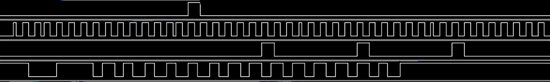
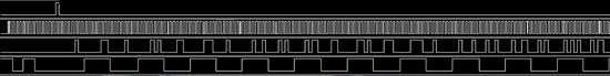
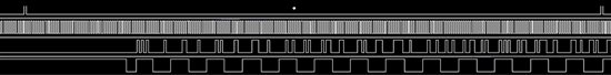
The McBPS0 is configured to 32 Timeslots, each timeslot is 8 bit. I feed on the CLKS pin 2.048MHZ. The BaudRate genretator creates the FSGX,CLKX signals. Using multichanel 8 partition mode.

The EDMA3 is configured to take data from a Ping/Pong buffer withouth chanel sorting and transmit to the DXR register.

My problem is: The EDMA will take the fist byte from the buffer and sent out. After that nothing happend. No more data are taken from the buffer and sent out.

Here is the code part what I use to configure the McBPS and EDMA3.  I do not use the DSP/Bios.

------------------------------------------------------------------------------------------------------------


Uint32 tmp;

CFG_PINMUX1 = (CFG_PINMUX1 & 0x33CFFFF) | 0x1420000 ;

//Set McBPS0 pin in PINMUX


mcbspRegs0->SPCR=0; //Reset FSYNC,SampleRateGen


//Select External Clock on CLKS pin for Sample rate Gen


//Select FramePeriod,Framewidth

mcbspRegs0->SRGR = CSL_FMK(MCBSP_SRGR_FSGM,1)

| CSL_FMK(MCBSP_SRGR_FPER,255) ;

mcbspRegs0->PCR = CSL_FMK(MCBSP_PCR_CLKRM,1)

| CSL_FMK(MCBSP_PCR_CLKXM,1)

| CSL_FMK(MCBSP_PCR_FSRM,1)

| CSL_FMK(MCBSP_PCR_FSXM,1);

mcbspRegs0->RCR = CSL_FMKT(MCBSP_RCR_RWDLEN1,8BIT)

| CSL_FMK(MCBSP_RCR_RFRLEN1,31);

mcbspRegs0->RCR = CSL_FMKT(MCBSP_XCR_XWDLEN1,8BIT)


| CSL_FMK(MCBSP_XCR_XFRLEN1,31);


//Set Multichanel mode

mcbspRegs0->MCR = CSL_FMK(MCBSP_MCR_XMCME,1)

| CSL_FMK(MCBSP_MCR_RMCME,1);


mcbspRegs0->RCERE0 = 0xffffffff;

//Enable all RX 32 Timeslotes

mcbspRegs0->XCERE0 = 0xffffffff;

//Enable all TX 32 Timeslotes


//Take out from reset the Sample Rate Generator, eneble FSYNC generation

mcbspRegs0->SPCR = CSL_FMK(MCBSP_SPCR_GRST,1)

| CSL_FMK(MCBSP_SPCR_FRST,1);


//----Setup EDMA3 for PCM0------------------------------------

edma3ccRegs->EESR = 4;

//Enable Event for chanel 2( XEVT0);


//PaRam for Transmit -EDMA channel 2

edma3ccRegs->PARAMSET[2].OPT=0x00100000;

//Options TCINTEN set

edma3ccRegs->PARAMSET[2].SRC=(Uint32)TX_Buff_PCM0_PING; //Source Address transmit from here

tmp = (TSLOTS_PCM0 << 16) | 1; //BCNT =TSLOTS_PCM0, ACNT =1


edma3ccRegs->PARAMSET[2].A_B_CNT=tmp;

edma3ccRegs->PARAMSET[2].DST=(Uint32)&(mcbspRegs0->DXR);

//Dest Address. This is the DXR register Address

tmp = (1<<16) ;

//DestBIDX =1, SRCBIDX =0

edma3ccRegs->PARAMSET[2].SRC_DST_BIDX=tmp;

tmp = (TSLOTS_PCM0 << 16) | (((Uint32)&(edma3ccRegs->PARAMSET[64])&0xFFFF));


//BCNTRLD =TSLOTS_PCM0,LINk=Param[64]

edma3ccRegs->PARAMSET[2].LINK_BCNTRLD=tmp;

edma3ccRegs->PARAMSET[2].SRC_DST_CIDX=0;

//Src,DST Cindex

edma3ccRegs->PARAMSET[2].CCNT=1;

//C count value 1


//Reload PONG PaRam for Transmit -EDMA channel 2 (64)

edma3ccRegs->PARAMSET[64].OPT=0x00100000;

//Options TCINTEN set

edma3ccRegs->PARAMSET[64].SRC=(Uint32)TX_Buff_PCM0_PONG;

//Source Address transmit from here

tmp = (TSLOTS_PCM0 << 16) | 1; //BCNT =TSLOTS_PCM0, ACNT =1

edma3ccRegs->PARAMSET[64].A_B_CNT=tmp;

edma3ccRegs->PARAMSET[64].DST=(Uint32)&(mcbspRegs0->DXR);

//Dest Address. This is the DXR register Address

tmp = (1<<16) ;

//DestIDX =1, SRCBIDX =0

edma3ccRegs->PARAMSET[64].SRC_DST_BIDX=tmp;

tmp = (TSLOTS_PCM0 << 16) | (((Uint32)&(edma3ccRegs->PARAMSET[65])&0xFFFF));


//BCNTRLD =TSLOTS_PCM0,LINk=Param[64]

edma3ccRegs->PARAMSET[64].LINK_BCNTRLD=tmp;

//Link and BCNT reload value

edma3ccRegs->PARAMSET[64].SRC_DST_CIDX=0;

//Src,DST Cindex

edma3ccRegs->PARAMSET[64].CCNT=1;

//C count value 1


//Reload PING PaRam for Transmit -EDMA channel 2 (64)

edma3ccRegs->PARAMSET[65].OPT=0x00100000;

//Options TCINTEN set

edma3ccRegs->PARAMSET[65].SRC=(Uint32)TX_Buff_PCM0_PING;

//Source Address transmit from here

tmp = (TSLOTS_PCM0 << 16) | 1; //BCNT =TSLOTS_PCM0, ACNT =1

edma3ccRegs->PARAMSET[65].A_B_CNT=tmp;

edma3ccRegs->PARAMSET[65].DST=(Uint32)&(mcbspRegs0->DXR);

//Dest Address. This is the DXR register Address

tmp = (1<<16) ;

//DestIDX =1, SRCBIDX =0

edma3ccRegs->PARAMSET[65].SRC_DST_BIDX=tmp;

tmp = (TSLOTS_PCM0 << 16) | (((Uint32)&(edma3ccRegs->PARAMSET[64])&0xFFFF));


//BCNTRLD =TSLOTS_PCM0,LINk=Param[64]

edma3ccRegs->PARAMSET[65].LINK_BCNTRLD=tmp;

edma3ccRegs->PARAMSET[65].SRC_DST_CIDX=0;

//Src,DST Cindex

edma3ccRegs->PARAMSET[65].CCNT=1;

//C count value 1


//Enable Receiver, Transmitter

mcbspRegs0->SPCR = mcbspRegs0->SPCR

| CSL_FMK(MCBSP_SPCR_RRST,1)

| CSL_FMK(MCBSP_SPCR_XRST,1);

------------------------------------------------------------------------------------------------------------

What Do I miss ?


  • I forgot to mention that I use TMS320C6424.

    Regards

    Robert

  • The formatting of the code makes it pretty hard to know if I am catching what is going on, but it looks reasonable.

    When the first byte gets sent, does it go out on the McBSP data out bit okay?

    Is the McBSP showing XRDY = 1 or 0?

    Is DMA channel 2 enabled via EER?

  • Yes the first byte is sent ok.

    The McBSP shows XRDY = 1.

    The EDMA EER = 4. this means the channel 2 event arrived.

    I have found a small problem but that did not fixed my problem.  In the  XCR the FRLEN1 was not set to 32.

    I think there is a problem also in the McBSP setup because I tried the Pooling method to transmit data over the McBPS.

    When I set the Multichannel 8 bit partitoin  mode then only the first byte is sent out 32 time in a frame after frame sync.

    When  I do not use the multichannel mode then after each DXR update a new frame sync is comming and the DXR is sent out 32 times.

    How shoul I configure the McBSP to use 32 timelots each 8 bit and after the fram sync  allways Timesolt0, Timeslot1,...Timeos31 to come?

    How should I settup the EDMA to sent out a 32 byte buffer which represent one frame with 32 Timeslots?

    BR

    Robert. 

  • Robert Kemenes said:
    The McBSP shows XRDY = 1.

    This means that an event should have been sent to the EDMA to trigger the DMA channel to send another byte. XRDY should be cleared when that happens, so the fact that it is set means that the McBSP is ready for Tx data that has not been sent.

    Robert Kemenes said:
    The EDMA EER = 4. this means the channel 2 event arrived.

    Actually this means that the Event to drive DMA Channel 2 is enabled to trigger a transfer. If ER = 4, then an event has arrived and has not been serviced. You need to also look at SER, EMR, IPR, and look for any other EDMA3 64-bit registers that happen to have bit 2 set (like SER/SERH).

    Robert Kemenes said:
    How should I configure the McBSP . . . ?

    The McBSP User's Guide is the best place to get explanations like this. I could never do as good and accurate a job as the UG already has. If you have a question about a particular point in the UG, please let us know.

    Robert Kemenes said:
    How should I configure the EDMA . . . ?

    The EDMA3 User's Guide is the best place to get explanations like this.It includes examples and well-itemized action lists. If you have a question about a particular point in the UG, please let us know.

  • Hello.

    I have read and the values are:

    XRDY = 1

    EER =4

    SER =0

    EMR =0

    IPR =0


  • Please dump out the hex values of your EDMA parameter sets so I can have a look.  For parameter set 2 please get a dump before and after the McBSP has been enabled.

  • here is the PaRam set dump.

    before  the McBSP enable.

    01C04040: 80100000 10802A70 00200001 01D00004
    01C04050: 00010000 00204800 00000000 00000001

    after  the McBSP enable.

    01C04040: 80100000 10802A70 001E0001 01D00006
    01C04050: 00010000 00204800 00000000 00000001

    after 1 second.

    01C04040: 80100000 10802A70 001E0001 01D00006
    01C04050: 00010000 00204800 00000000 00000001

    I have seen that the BCNT value was decremented, but only to value 0x1e.


  • Robert Kemenes said:

    mcbspRegs0->RCR = CSL_FMKT(MCBSP_RCR_RWDLEN1,8BIT)

    | CSL_FMK(MCBSP_RCR_RFRLEN1,31);

    mcbspRegs0->RCR = CSL_FMKT(MCBSP_XCR_XWDLEN1,8BIT)


    | CSL_FMK(MCBSP_XCR_XFRLEN1,31);

    Looks like you have a typo in your code.  That might be your issue.  I don't think you've ever configured XCR.  You should dump out the McBSP regs to verify.

  • I know that error. and I already have fixed that in the first day.

    Here is the McBSP dump.

    01D00000: 000000AA 0000AAAA 00C30003 00001F00
    01D00010: 00001F00 10FF0000 00000000 00000000
    01D00020: 00000000 00000F00 00000000 00000000
    01D00030: 00000000 00000000 00000000 00000000


  • What do you see with a scope on the McBSP pins?  Is there an output on CLKX/CLKR?  FSX/FSR?  What frequencies?  Do you see any data come out?

    Also, I recommend adjusting your McBSP initialization to follow the procedure given in Section 2.11 "McBSP Initialization Procedure" of the McBSP User Guide.

    It looks like the EDMA has transferred 2 elements.  This would fill the XSR and DXR registers.  If for some reason the McBSP were not actually transmitting that's where I would expect things to stop.

  • on the CLKX ping I have the same frequenci what I feed to the CLKS input pin which is. 2,048MHZ which represent 32 timesolt with frame sync 125KHZ.

    On the FSX pin I get the Frame sync pulse after each 32 byte frame.

    On the DX pin is sent out the first byte what was taken from the buffer by EDMA, but in one frame I have this first byte 32 times!. I can make a picture with a logic analyzer and send it if you need it.

    I guess there is some small problem with the McBSP configuration,but I used the User Manual to make this setup.


  • (Side note: You have the last post marked as "Verified Answer".  That is used to indicate that your problem has been resolved.  Assuming that's not the case I assume you go back and click "Reject Answer".  Otherwise other engineers won't bother looking in this thread because the little green checkmark will make it look like your problem is already solved!)

    Have you tried using the CPU to service the McBSP?  That would help determine whether your issue is in the McBSP or EDMA.

  • yes I tried the pooling methode, but in the user's guide tehre is a note that the XRDY bit should be checked with the period of CLKX and not with the period of CPU clock.

    I can check only with the period of cpu clock.

    also when I service the McBSP with the cpu there are some problemes. If the McBSP is not configured in multichannel mode, then after each frame sync a new byte is sent out 32 times.

    it look like this: FS B0, B0,B0,...B0     FS B1,B1,B1,....B1    FS B2, B2,B2,..B2

    If the multichannel mode is configured then the first byte is sent out 32 times.

    FS B0,B0,B0,...B0   FS B0,B0,B0,...B0   FS B0,B0,B0,...B0

    This is the code what I sued to send out the data using pooling mode,

    for(i=0;i<32;i++)

    {

      do

          {

            t=(mcbspRegs0->SPCR);

          }

          while((t&0x20000)!= 0x20000);

          mcbspRegs0->DXR = TX_Buff_PCM0_PING[i];

      }

  • I have found out some problems, using pooling mode. but does not solve my problem totally.

    I made some screenshoots from a logic analyzer.

    In the logic anayzer the first signal is the FSX, the second signal is the CLKX, the Third is the TXD out, and the fourh signal is an indicator that flip  when the XRDY=1.

    I have found out that after McBSP setup the McBSP is not yet ready to send bytes. I have to wait at least the first frame sync.

    This is in the 32 byte send buffer. aa,02,03,04,05,06,07,08,0a,0b,0c,0d,......

    Withouth Delay between McBSP setup and send data with pooling mode. You can see theTXRDY = 1 after each 2 CLCX cycles.

    With a short delay( which is not yet enough) here the firs bytes are missed.


     With Big delay. Now every bytes are sent, but unfortunaltelly they are not syncronized to the Fram Sync signal. The firs byte should start after the Framy sync signal.

  • Robert Kemenes said:
    With Big delay. Now every bytes are sent, but unfortunaltelly they are not syncronized to the Fram Sync signal. The firs byte should start after the Framy sync signal.

    You need to correct your initialization procedure as I already mentioned.  There's a specific order to take the pieces of the McBSP out of reset and you are not following it.

  • Hello

    I have followed the initialization sequence from the user guide, and corrected a small progblem in the EDMA config, and now the McBSP running perfectly.

    Then you for your support.

    I still have a question only for my info.

    In the EDMA userguide (SPRUEM5A) page 72 there is a McBSP example for continous operation with channel sorting. How tha will do the channel sorting ?

    Why the CCNT = 0xFFFF ?

    Best regards.

    Robert Kemenes

  • Robert Kemenes,

    It is awesome that you have your system working, or at least that portion of it.

    I would like to ask two favors of you: 1) click Verify Answer on Brad (Superman) Griffis' post above that helped you with your final answer, and 2) post this new question to a new thread then post back here with a link to the new one.

    I apologize for adding to your work, but this will help get the error reported to the factory documentation group, it will be much easier for us to get attention on this error in the EDMA UG this way. And it needs to be fixed, probably in a dozen or more EDMA3 UG's.

    The correct PaRAM settings for a single buffer-pair with channel sorting would need the following changed from this example:

    BCNT=2 // this is the number of channels to be extracted from the rx stream
    CCNT=LEN // this is the length in samples of each of the two separate channel buffers
    BCNTRLD=2  // this should match BCNT
    DSTBIDX=distance in bytes from Abuf to Bbuf
    DSTCIDX=distance back from Bbuf to ABuf minus ACNT

    The next example with ping pong buffering is also incorrect, and ping pong buffering is much more common and useful than just a single buffer.