This thread has been locked.

If you have a related question, please click the "Ask a related question" button in the top right corner. The newly created question will be automatically linked to this question.

TMS320C5505: fft frequency doesnot match with the actual signal frequency

Part Number: TMS320C5505


Dear ,

to calculate frequency from HWAFFT output i followed ur instructions as mentioned below by :

The FFT transforms a time-domain signal into the frequency domain (and visa versa). The FFT operates with a power-of-2 number of bins each representing a range of frequencies. The width of each bin depends on the sampling rate that was used to capture the time-domain signal and the number of FFT bins: each bin width = Sampling rate / number of bins. Take for example a 16-pt FFT of a signal that was sampled with a sampling rate of 1MHz. Each bin of the 16-point FFT is 62.5 kHz wide (1MHz / 16), starting at 0Hz (DC) going all the way to the sampling rate 1MHz.

I am using the sampling frequency as 2MHz by setting *SARCLKCTRL = 0x0031; and 1024point FFT.

so by calculation ,  Bin frequency= 2MHz/1024=1953.125 Hz.

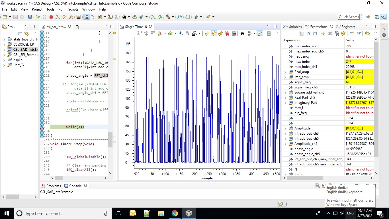
i get the maximum magnitude at 511th bin then frequency should be 511*1953.125=998046.87 Hz

but the problem is my actual signal frequency is 48.12Hz 

so the actual signal frequency does not match with the frequency by FFT,..

kindly consult me..am i on the right path??


  • Hi,

    I've notified the rtos team. They will post their feedback directly here.

    Best Regards,
    Yordan
  • Hi Kanchan,

    When you set SARCLKCTRL to 0x0031, the SAR_CLK frequency is SYSCLK / 49d. But each conversion takes 32 SAR clock cycles, so the sampling rate is actually 63.776kHz (100MHz / 49 / 32, I believe your SYSCLK frequency is 100MHz). 64 kilo-samples per second (ksps) is the maximum frequency that the SAR can operate at.

    So when you take the 1024-pt FFT with a 63.776kHz sampling rate (fS), the resolution of each frequency bin is 62.28Hz. And the Nyquist frequency is 31.888kHz.

    So the FFT result shows the frequency spectrum in 512 bins (each 62.28 Hz wide) from 0Hz to 31.888kHz.

    Does this make better sense? Is the frequency of interest contained in your input signal below 31.888kHz?

    Linking these similar threads together:
    e2e.ti.com/.../2473134
    e2e.ti.com/.../2482150
    e2e.ti.com/.../662931

    Hope this helps,
    Mark
  • Thank u so much sir for kind response...i completely understood..but the frequency of interest contained in my input signal below 31.888kHz. It is 48.45Hz ..so what should be the sampling frequency???

    so what can i do???

  • Why don't you slow down the sampling rate to something like 512Hz. Then you can measure frequencies upto 256Hz, and have a resolution of 0.5Hz per FFT bin with an 1024-pt FFT

    Use SARCLKCTRL to 0x17D7 to divide 100MHz SYSCLK by 6103d to have a SAR_CLK of 16.385kHz.
    Since it takes 32 SAR_CLK cycles to perform a conversion, the sampling rate is 512.04Hz.
    Frequency width per bin is 0.500 Hz.
    So a 48.45Hz tone should appear in bin 96 or 97 of 1024.

    Hope this helps,
    Mark
  • Dear Mark,

    Thank u..but see i set the sample rate=512Hz i will get only 16 samples per sec (since 62500 samples per sec for 2MHz of sampling rate)

    so 1 sample in 63ms but my one sinewave cycles is 48.45Hz i.e 19.53ms...

    so i think its completely contradictory..because to calculate 1024 point FFT i need to collect 1024 samples in one cycle i.e. in 20ms.

  • Hi Kanchan,

    I think you arrived at the 16 samples per sec by dividing 512 by 32 (512/32 = 16).

    But the 512Hz sampling rate from above is after the 32 SAR_CLK cycles required for each sample.

    The SAR_CLK rate is 16.385kHz and the actual sampling rate is ~512Hz. (16385 / 32 = 512.03)

    This allows you to sample anything lower than 256Hz and it will take 2 seconds to capture 1024 samples that you can supply into the 1024-pt FFT.

    Feel free to run things faster, or use a smaller FFT length if you are limited to capturing samples for less than 2 seconds.

    Hope this helps,
    Mark

  • Ohk i got it Mark..still i am not getting the exact frequency of the signal..I dont understand whats wrong..following is my FFT calculation function.

    double FFT_ch3(Int32 *data)
    {
    /*______________________________________________________________________________________*/

    Int32 *result;
    float *result1;
    Int16 i;
    Int32 *scratch=scratch_buf;
    Int32 *data_br=data_br_buf;

    fft_flag = FFT_FLAG;
    scale_flag = NOSCALE_FLAG;

    /*______________________________________________________________________________________*/

    hwafft_br(data, data_br, DATA_LEN_1024); /* bit-reverse input data */

    data=data_br;

    out_sel = hwafft_wrapper(data,scratch,fft_flag,scale_flag,hwafft_1024pts);

    if (out_sel == OUT_SEL_DATA)
    {
    result = data;

    for(i=0;i<DATA_LEN_1024;i++)
    {
    Real_Part[i] =data[i] & 0x0000FFFF;
    Imaginary_Part[i] = data[i] >> 16;

    }
    }
    if(out_sel==OUT_SEL_SCRATCH)
    {
    result = scratch;
    for(i=0;i<DATA_LEN_1024;i++)
    {
    Real_Part[i] =scratch[i] & 0x0000FFFF;
    Imaginary_Part[i] = scratch[i] >> 16;

    }
    }


    /*to find the amplitude of the FFT output array*/
    for(i=0;i<(DATA_LEN_1024/2);i++)
    {
    Real_amp[i]= Real_Part[i] * Real_Part[i];
    Img_amp[i]= Imaginary_Part[i] * Imaginary_Part[i];
    Square_add_val[i]=Real_amp[i]+Img_amp[i];
    Amplitude[i]= sqrt(Square_add_val[i]);
    }


    //to find the index at which amplitude is highest
    max_index=find_high_index(Amplitude, (DATA_LEN_1024/2));


    Imag_No=Imaginary_Part[max_index];
    Real_No=Real_Part[max_index];

    //to find the frequency where amplitude is highest
    signal_freq=Freq_cal(max_index,Amplitude, (DATA_LEN_1024/2));

    //to find the phase angle where amplitude is highest

    phase_angle=atan(value);
    phase_angle=(phase_angle*180)/PI;
    return phase_angle;
    }

    /*======================================================================================================================*/
    /*Function to find index where the magnitude is maximum*/
    Int32 find_high_index(Int32 Amplitude[], Int16 N)
    {

    Int32 i, max_i = 0;
    Int32 max_amp = Amplitude[0];
    for(i = 0; i < N; i++)
    {
    if(Amplitude[i] >= max_amp)
    {
    max_amp = Amplitude[i];
    max_i = i;
    }
    }
    return max_i;

    }


    /*=========================================================================================================================*/
    /*since th esampling frequency is 2MHz and 8pt FFT*/
    /*bin_frequncy=(2MHz/8)= 250000Hz=250 KHz*/
    /*to find the signal frequency=max_index * bin frequency*/
    Int32 Freq_cal(Int32 max_i,Int32 Amplitude[],Int16 N)
    {

    Int32 frequency=0,bin_freq;
    Int32 i;
    Int32 max_amp = Amplitude[0];
    // bin_freq= (256/DATA_LEN_1024)=4; //
    if(max_i==0)
    {
    for(i = 1; i<N; i++)
    {
    if(Amplitude[i] >= max_amp)
    {
    max_amp = Amplitude[i];
    max_i = i;
    }
    }
    frequency= (max_i/4) ;
    }
    else
    {
    frequency= (max_i/4);
    }
    return frequency;

    }

    /*====================================================================================================*/

    OUTPUT is attached. Graphs of FFT magnitude, ADC signal.

  • Please Reply

  • can u plz tell me how do i write the code for block floating point for fixed point dsp i.e tms320c5505. to implement FFT coding so that i get the result..i got a document from TI 

    SPRA948 − September 2003
    1
    A Block Floating Point Implementation for an N-Point FFT
    on the TMS320C55x DSP


    but i dont understand how to implement it in my code or in in built hwafft code of tms320c5505.


    plzzzz reply

  • waiting for response

  • Hi Kanchan,

    I'm concerned about the number format.

    The input and output vectors of the HWAFFT contain complex numbers. Each real and imaginary part is represented by a two’s complement, 16-bit fixed-point number. The most significant bit holds the number’s sign value, and the remaining 15 are fraction bits (S16Q15 format). The range of each number is [-1, 1 – (1/2)15]. Real and imaginary parts appear in an interleaved order within each vector.

    To extract the real and imaginary parts from the complex vector, it is necessary to mask and shift each 32-bit element into its 16-bit real and imaginary parts:
    Uint16 Real_Part = CMPLX_Vec32[i] >> 16;
    Uint16 Imaginary_Part = CMPLX_Vec32[i] & 0x0000FFFF;

    You have this part backwards...
    Real_Part[i] =data[i] & 0x0000FFFF;
    Imaginary_Part[i] = data[i] >> 16;

    You must also put the input vector in this format
    Int32 *data // all data buffers must be aligned in memory see appendix of SPRABB6 for methods
    for (i=0;i<FFTLENGTH;i++)
    {
    data[i] = 0; // clear imag part and zero pad if data buff less than FFTLENGTH
    if(i < DATABUFLEN)
    data[i] |= inputbuf[0] << 16; // push 16-bit input vector data into real part of data buf before HWAFFT
    }

    When you graph the input data, you should skip over the imag parts and graph only the real parts. To do this, use 16-bit signed integer data type, Index Increment 2 (to skip over imag parts), and set the Q value to 15 (since there are 15 quotient/fraction bits). Then the input should be centered about 0 and should be in the range -1 to 0.9999. This will verify the input signal is correct. The same settings can be used to graph to the output signals.

    Your graph shows the input signal range from decimal 0 to 325. That seems to have a DC offset and small amplitude. If you are getting these numbers from the SAR ADC, then the input signal to the SAR should be centered about VREF / 2. The SAR ADC outputs are in the range from decimal 0 to 1023 (10-bit SAR ADC). Without remapping the numbers to 2's complement Q15, I would expect FFT bin 0 to be large due to DC offset. A typcial audio codec like AIC3204 will provide you native 16-bit 2's complement signed fractional numbers centered about 0.

    Regards,
    Mark
  • Hi Kanchan,

    The use of Block Floating Point (BFP) is an advanced technique used for scaling in the FFT example. It would only be required if you run out of dynamic range with the fixed point number system (perhaps when scaling at every FFT stage).
    To implement the BFP with HWAFFT, you would have to modify the hwafft assembly/copr commands (eg. hwafft_16pts) to insert scaling code between the execution of each stage. One catch is that the HWAFFT increases efficiency by performing two FFT processing stages in one go (double stages). If the number of stages is odd (like 8-bit and 32-bit FFTs), then a single stage is performed at the end instead of a double stage.
    The comments in hwafft.asm show where the each double (and single) stage begins - where you can add your own scaling code (BFP for example).

    Personally, I would saturate the usefulness of the HWAFFT before attempting to integrate BFP.

    Regards,
    Mark