This thread has been locked.

If you have a related question, please click the "Ask a related question" button in the top right corner. The newly created question will be automatically linked to this question.

RTOS/AM5728: 3-wire SPI driver

Part Number: AM5728

Tool/software: TI-RTOS

Hi I have an RF device RF 20252 connected to AM 5728 on SPI. Im trying to write a slave driver for this RF. The AM5728 is  connected using only 3 wires, only chip select, clk and data (either D0 or D1) from AM 5728 to RF. Given below is the diagram showing interfacing of the rF device to a typical controller and the corresponding write and read timing diagrams.
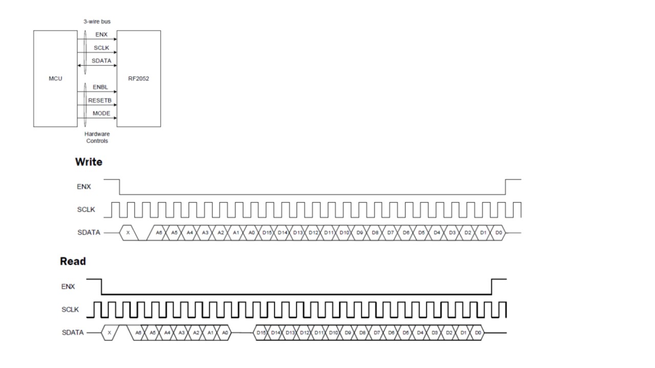
As shown in the diagram above, the chip select has to go low after 1 clock cycle and remain low for the entire transaction. In case of the write transaction, a start bit is followed by a 0 to indicate write transaction, followed by the actual Address and data.  The read follows a similar pattern with the difference that after the address is sent, the driver will get the read data only after 2 clock cycles. Following are the questions that i had:

a>Will the above protocol be supported by SPI master on AM 5728? 

b>How do i ensure that Chip select is delayed by 1 clock cycle?

c>Only 1 data line gets used for read as well as write. Does this mean i have to use the SPI master in half duplex mode? In case of read, it means i first set up the SPI master in tx_only mode to write the address and then set it up in rx_only mode to read the data?

d>Is there any reference example available for similar usage of SPI? the PDK example does not use SPI in the same manner?

  • The RTOS team have been notified. They will respond here.
  • Sandeep,

    I have looped in the HW expert to comment on feasibility of the AM572x-RF20252 interface using McSPI. If you have configured AM572x as SPI master then you can use the SPI chip select timing control but this seems to be available only in 4 pin mode (Refer to TRM).

    From the software perspective, the examples that we have provided with the PDK, demonstrate the MCSPI in master mode are reading data from GPIOs from industrial IO lines and also have a master slave example which uses 2 AM57xx IDK connected back to back as described here:
    processors.wiki.ti.com/.../Processor_SDK_RTOS_QSPI-McSPI

    All the examples in the PDK are using 4 pin mode, CLK, 2 data lines and CS.

    Regards,
    Rahul
  • Hi Sandeep,

    It looks like your Chip Select (CS) line for Read needs to be delayed only when CS is removed (and not when it is asserted). Unfortunately, when the AM5728 SPI adds a delay, the delay occurs when CS is both asserted and removed. It is symmetrical and not independent. This is described further in the "Chip-Select Timing Control" section of the TRM.

    Regards,
    Melissa