This thread has been locked.

If you have a related question, please click the "Ask a related question" button in the top right corner. The newly created question will be automatically linked to this question.

Linux/AM3352: SPI configuration issue

Part Number: AM3352
Other Parts Discussed in Thread: SN65HVS882

Tool/software: Linux

Hi,

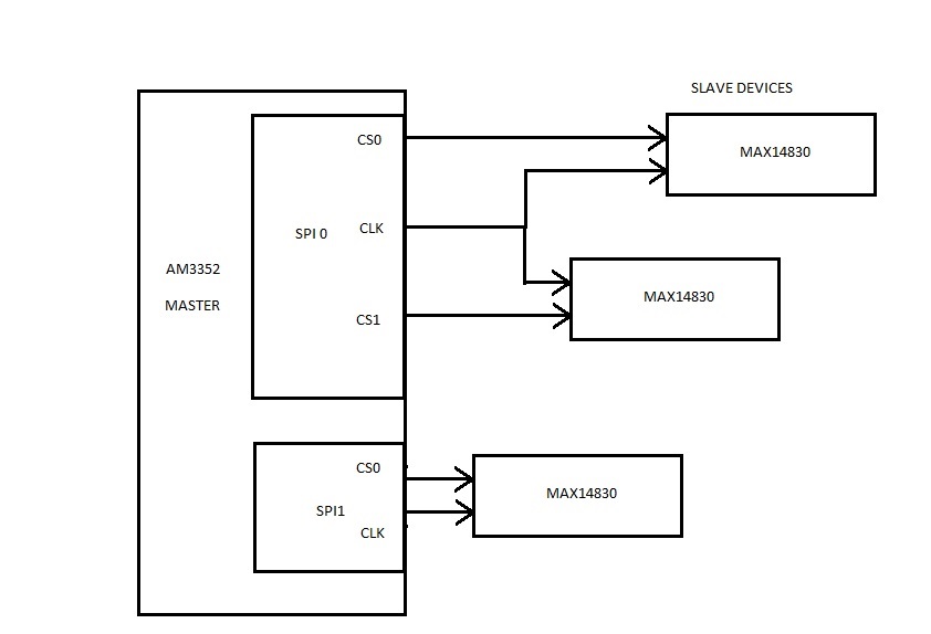
     We have a custom board with AM3352 processor. we connected three MAX14830 (SPI to QUAD Uart IC). AM3352 is configured as MASTER . We are using ti-sdk only.                                                                             Linux Version:  linux-4.4.41+gitAUTOINC+f9f6f0db2d-gf9f6f0db2d, Diagramatic representation is given bellow of our design,

I Have configured the Pin Mux. Given Bellow for the reference,

spi1_pins: myspi1_pins_default {
pinctrl-single,pins = <
AM33XX_IOPAD(0x950, PIN_INPUT_PULLUP | MUX_MODE0 ) /* (A17) spi0_sclk.spi0_sclk */
AM33XX_IOPAD(0x954, PIN_INPUT_PULLUP | MUX_MODE0 ) /* (B17) spi0_d0.spi0_d0 */
AM33XX_IOPAD(0x958, PIN_INPUT_PULLUP | MUX_MODE0 ) /* (B16) spi0_d1.spi0_d1 */
AM33XX_IOPAD(0x95c, PIN_INPUT_PULLUP | MUX_MODE0 ) /* (A16) spi0_cs0.spi0_cs0 */
AM33XX_IOPAD(0x960, PIN_INPUT_PULLUP | MUX_MODE0 ) /* (C15) spi0_cs1.spi0_cs1 */
>;
};

spi2_pins: myspi2_pins_default {
pinctrl-single,pins = <
AM33XX_IOPAD(0x908, PIN_OUTPUT_PULLUP | MUX_MODE2 ) /* (H16) gmii1_col.spi1_sclk */
AM33XX_IOPAD(0x90c, PIN_OUTPUT_PULLUP | MUX_MODE2 ) /* (H17) gmii1_crs.spi1_d0 */
AM33XX_IOPAD(0x910, PIN_INPUT_PULLUP | MUX_MODE2 ) /* (J15) gmii1_rxer.spi1_d1 */
AM33XX_IOPAD(0x944, PIN_OUTPUT_PULLUP | MUX_MODE2 ) /* (H18) rmii1_refclk.spi1_cs0 */
AM33XX_IOPAD(0x964, PIN_OUTPUT_PULLUP | MUX_MODE2 ) /* (C18) eCAP0_in_PWM0_out.spi1_cs1 */

Changes has been made in the dts file 

&spi0 {
#address-cells = <1>;
#size-cells = <0>;

pinctrl-names = "default";
pinctrl-0 = <&spi1_pins>;
cs-gpios = <&gpio0 5 0>, <&gpio0 6 0>;
ti,pindir-d0-out-d1-in = <1>;
spi-cpha;
spi-cpol;
status = "okay";

U6: max14830@0 {
compatible="maxim,max14830";
reg = <1>;
mode = <0>;
spi-max-frequency=<26000000>;
clocks=<&clk4m>;
clock-names="osc";
interrupt-parent=<&gpio3>;
interrupts=<15 8>;
gpio-controller;
#gpio-cells = <2>;
status = "okay";
};

};

&spi1 {

#address-cells = <1>;
#size-cells = <0>;

pinctrl-names = "default";
pinctrl-0 = <&spi2_pins>;
ti,pindir-d0-out-d1-in = <1>;
spi-cpha;
cs-gpios = <&gpio0 5 0>, <&gpio0 6 0>;
ti,pindir-d0-out-d1-in = <1>;
spi-cpha;
spi-cpol;
status = "okay";

U5: max14830@1 {
compatible = "maxim,max14830";
reg = <1>;
mode = <0>;
spi-max-frequency = <26000000>;
clocks = <&spi_uart_clk>;
clock-names = "osc";
//interrupt-parent = <&gpio3>;
//interrupts = <14 0x2>;
gpio-controller;
#gpio-cells = <2>;
};

U4: max14830@1 {
compatible = "maxim,max14830";
reg = <0>;
mode = <0>;
spi-max-frequency = <26000000>;
clocks = <&spi_uart_clk>;
clock-names = "osc";
//interrupt-parent = <&gpio3>;
//interrupts = <21 0x2>;
gpio-controller;
#gpio-cells = <2>;
};

};

Questions:

1. We are not getting the Clock and Chip select signal ?

2. Any changes has to be done in driver ?

3. Any changes has to be do in device tree ?

4. What can be the issue?

  • Hi Avinash,

    Avinash Neethi1 said:

    &spi0 {
    #address-cells = <1>;
    #size-cells = <0>;

    pinctrl-names = "default";
    pinctrl-0 = <&spi1_pins>;
    cs-gpios = <&gpio0 5 0>, <&gpio0 6 0>;
    ti,pindir-d0-out-d1-in = <1>;
    spi-cpha;
    spi-cpol;
    status = "okay";

    U6: max14830@0 {
    compatible="maxim,max14830";
    reg = <1>;
    mode = <0>;
    spi-max-frequency=<26000000>;
    clocks=<&clk4m>;
    clock-names="osc";
    interrupt-parent=<&gpio3>;
    interrupts=<15 8>;
    gpio-controller;
    #gpio-cells = <2>;
    status = "okay";
    };

    };

    From the diagram you have provided I see you have two MAX14830 chips on McSPI0, one on CS0 and one on CS1. But in the DTS node for McSPI0 you described only one MAX14830 chip at CS0/CS1 at the same time. You are missing second MAX184830 chip on McSPI0/CS1 in your DTS file.

    If diagram is correct, please update to:

    U6: max14830@0 {
    compatible="maxim,max14830";
    -reg = <1>;
    +reg = <0>;

    U7: max14830@1 {
    compatible="maxim,max14830";
    reg = <1>;
    ....

    Refer to the below DTS for example. It described two chips (SPI flash W25Q64, SN65HVS882) attached to McSPI0 CS0 and CS1.

    linux-kernel/arch/arm/boot/dts/am335x-icev2.dts

    Avinash Neethi1 said:

    &spi1 {

    #address-cells = <1>;
    #size-cells = <0>;

    pinctrl-names = "default";
    pinctrl-0 = <&spi2_pins>;
    ti,pindir-d0-out-d1-in = <1>;
    spi-cpha;
    cs-gpios = <&gpio0 5 0>, <&gpio0 6 0>;
    ti,pindir-d0-out-d1-in = <1>;
    spi-cpha;
    spi-cpol;
    status = "okay";

    U5: max14830@1 {
    compatible = "maxim,max14830";
    reg = <1>;
    mode = <0>;
    spi-max-frequency = <26000000>;
    clocks = <&spi_uart_clk>;
    clock-names = "osc";
    //interrupt-parent = <&gpio3>;
    //interrupts = <14 0x2>;
    gpio-controller;
    #gpio-cells = <2>;
    };

    U4: max14830@1 {
    compatible = "maxim,max14830";
    reg = <0>;
    mode = <0>;
    spi-max-frequency = <26000000>;
    clocks = <&spi_uart_clk>;
    clock-names = "osc";
    //interrupt-parent = <&gpio3>;
    //interrupts = <21 0x2>;
    gpio-controller;
    #gpio-cells = <2>;
    };

    };

    From the diagram you have provided I see you have one MAX18430 chip on McSPI1/CS0. But your DTS file describe two MAX18430 chips. Please fix that also.

    I also see some properties in max14830 nodes that are not supported (i.e. spi-max-frequency). Refer to the below file regarding the supported properties of the max14830 node:

    linux-kernel/Documentation/devicetree/bindings/serial/maxim,max310x.txt

    Regards,
    Pavel

  • Hi Pavel,

    In Diagram i made a mistake, In SPI0 only one Max 14830 and in SPI2 two Max 14830 IC are connected. Clock and CS pins are not triggered even single Iteration.

    We have also made the changes as specified in the linux-kernel/Documentation/devicetree/bindings/serial/maxim,max310x.txt. 

    CS and CLK pin are in active low state only from power on condition 

    Waiting for a positive reply to solve the issue,

    Rehards,

    Avinash N

  • Avinash,

    Avinash Neethi1 said:

    n Diagram i made a mistake, In SPI0 only one Max 14830 and in SPI2 two Max 14830 IC are connected. Clock and CS pins are not triggered even single Iteration.

    We have also made the changes as specified in the linux-kernel/Documentation/devicetree/bindings/serial/maxim,max310x.txt. 

    Please provide the updated DTS file for review.

    Regards,
    Pavel

  • Hi Pavel,

    In Our Custom Board, We have connected one MAX14830 in SPI0(in CS1) and two MAX14830 in SPI1 (in CS0 and CS1). I Have attached the Updated DTS For Your Reference, 

    &spi0 {
    #address-cells = <1>;
    #size-cells = <0>;

    pinctrl-names = "default";
    pinctrl-0 = <&spi1_pins>;
    ti,pindir-d0-out-d1-in = <1>;
    status = "okay";

    U6: max14830@1 {
    compatible="maxim,max14830";
    reg = <1>;
    mode = <0>;
    spi-max-frequency=<12000000>;
    clocks=<&spi_uart_clk>;
    clock-names="osc";
    interrupt-parent=<&gpio3>;
    interrupts=<15 0x2>;
    gpio-controller;
    #gpio-cells = <2>;
    status = "okay";
    spi-cs-high;
    };
    };


    &spi1 {

    #address-cells = <1>;
    #size-cells = <0>;

    pinctrl-names = "default";
    pinctrl-0 = <&spi2_pins>;
    ti,pindir-d0-out-d1-in = <1>;
    status = "okay";

    U5: max14830@1 {
    compatible = "maxim,max14830";
    reg = <1>;
    mode = <0>;
    spi-max-frequency = <26000000>;
    clocks = <&spi_uart_clk>;
    /* clocks = <0x44>; */
    clock-names = "osc";
    interrupt-parent = <&gpio3>;
    interrupts = <14 0x2>;
    gpio-controller;
    #gpio-cells = <2>;
    spi-cs-high;
    };

    U4: max14830@0 {
    compatible = "maxim,max14830";
    reg = <0>;
    mode = <0>;
    spi-max-frequency = <26000000>; 
    clocks = <&spi_uart_clk>;
    /* clocks = <0x44>; */
    clock-names = "osc";
    interrupt-parent = <&gpio3>;
    interrupts = <21 0x2>;
    gpio-controller;
    #gpio-cells = <2>;
    spi-cs-high;
    };

    };

    This is the currently using DTS File. 

    From Processor the Clock is not getting generated. What Can Be the issue ?

    From Processor the CS is not getting generated . What Can Be the issue?

    Regards,

    Avinash N

  • Avinash,

    Avinash Neethi1 said:
    In Our Custom Board, We have connected one MAX14830 in SPI0(in CS1) and two MAX14830 in SPI1 (in CS0 and CS1).

    Let we first focus on SPI0. Once fixed we can continue with SPI1 (if needed).

    Avinash Neethi1 said:
    &spi0 {

    Avinash Neethi1 said:
    ti,pindir-d0-out-d1-in = <1>;

    You select D0 pin as output and D1 pin as input, but this does not match your pinmux, where you set both D0/D1 pins as inputs. You should fix that.

    AM33XX_IOPAD(0x954, PIN_INPUT_PULLUP | MUX_MODE0 ) /* (B17) spi0_d0.spi0_d0 */
    AM33XX_IOPAD(0x958, PIN_INPUT_PULLUP | MUX_MODE0 ) /* (B16) spi0_d1.spi0_d1 */

    Avinash Neethi1 said:
    mode = <0>;

    What does this "mode" property do? I can not find such optional property in dts documentation:

    linux-kernel/Documentation/devicetree/bindings/serial/maxim,max310x.txt

    linux-kernel/Documentation/devicetree/bindings/spi/omap-spi.txt

    linux-kernel/Documentation/devicetree/bindings/spi/spi-bus.txt

    Avinash Neethi1 said:
    From Processor the Clock is not getting generated. What Can Be the issue ?

    Do you mean you do not have clock signal on AM335x pin SPI0_SCLK? Check first if AM335x McASP module is properly enabled in PRCM registers, check register values CM_PER_SPI0_CLKCTRL. Check also register value conf_spi0_sclk and MCSPI_SYST.

    Regards,
    Pavel

  • Hi pavel,

    1. You select D0 pin as output and D1 pin as input, but this does not match your pinmux, where you set both D0/D1 pins as inputs. You should fix that.

    I have changed the pin-mux as per the recomendation.

    AM33XX_IOPAD(0x954, PIN_OUTPUT_PULLUP | MUX_MODE0 ) /* (B17) spi0_d0.spi0_d0 */
    AM33XX_IOPAD(0x958, PIN_INPUT_PULLUP | MUX_MODE0 ) /* (B16) spi0_d1.spi0_d1 */

    2. I have just added with reference to old version kernel. I have removed the mode section.

    Regards,
    Avinash N