This thread has been locked.

If you have a related question, please click the "Ask a related question" button in the top right corner. The newly created question will be automatically linked to this question.

RTOS/TMDXICE110: SPI bootloader doesn’t work

Part Number: TMDXICE110
Other Parts Discussed in Thread: AM3359, AMIC110

Tool/software: TI-RTOS

I tried to get the AMIC-specific bootloader to run on the TMDXICE110. Following your guide, I could not get that to work, although I tried various combinations of parameters. At some point, I tried the AM335x-EVM bootloader – which works instantly fine, in contrast.

1) Can you tell me, why the AMIC bootloader doesn’t work?

2) Is there any downside of using the AM335x-EVM bootloader?

3) What exactly is the purpose of `-s KW_BUILD=no`?

4) Is the AMIC bootloader able to use DDR at all? Due to the name being "amic110-ddrless", I am not able to tell if that bootloader works XIP-only, or if that’s just the default, and if "USE_DDR=yes" does have any effect, at all.

5) Loading larger projects like the profinet example is incredible slow and takes several minutes. Is it possible to speed that up?

6) Have I understood the usage of `tiimage` correctly, that it is just necessary to specify `mcspi` as the second parameter for the bootloader and `NONE` as the second parameter for the application?

7) Why does starterware/platform.mk specify `IMG_LOAD_ADDR = 0x40300000` even though it’s quite the same as the AM3359 and for those `IMG_LOAD_ADDR = 0x80000000` is specified?

8) Whenever I use my compiled version of `tiimage` and specify 0x80000000, I see in the UART output of the bootloader `dst = 0x80`. Why does this get cut off? When I load the precompiled binaries of starterware, `dst` always is shown as `0x80000000`. The precompiled starterware examples also have 0x80000000 compiled into their binary header and they are the only binaries, I can get to run on my AMIC board.

9) Additionally, the displayed size in the bootloader is far too big, whereas "spi_flash_writer" displays the correct size at loading. For example "spi_flash_writer" states "Erasing flash at byte offset: 131072, byte length: 1396736 // […] // SF: Successfully erased 1396736 bytes @ 0x175000 // Writing flash at page offset: 512, number of pages: 5445" at loading a file of size 1.393.736 Bytes (so somehow 6.000 Bytes get added?). But the bootloader then displays "offset = 0x20008, size = 0x48441500, dst = 0x80" at loading the payload (what corresponds to 1.212.421.376 bytes).

10) Could you please explain me how I can achieve a correct `*_ti.bin` file? `tiimage 0x80000000 mcspi <file>.bin <file>_ti.bin ` doesn’t work for me, as explained above. The bootloader also hangs directly after "Copying image from flash to DDR" (what but works with the precompiled starterware example binaries).

The example starterware binary I used is "[…]/pdk_am335x_1_0_9/packages/ti/starterware/binary/gpio_app_led_blink/bin/am335x-evm/gcc/gpio_app_led_blink_a8host_debug_ti.bin", which has the size 55.120 Bytes. "spi_flash_writer" says "Erasing flash at byte offset: 131072, byte length: 57344 // […] // SF: Successfully erased 57344 bytes @ 0x2e000 // Writing flash at page offset: 512, number of pages: 216". The bootloader says "Copying image from flash to DDR // offset = 0x20008, size = 0xd750, dst = 0x80000000" (which means exactly 55.120 Bytes, what also is the real size of the binary, with the header included).

  • The RTOS team have been notified. They will respond here.
  • Frank,

    Frank Brütting said:

    1) Can you tell me, why the AMIC bootloader doesn’t work?

    2) Is there any downside of using the AM335x-EVM bootloader?

    3) What exactly is the purpose of `-s KW_BUILD=no`?

    4) Is the AMIC bootloader able to use DDR at all? Due to the name being "amic110-ddrless", I am not able to tell if that bootloader works XIP-only, or if that’s just the default, and if "USE_DDR=yes" does have any effect, at all.

    All AM335x and AMIC110 users are required to use the AM335x-EVM bootloader. The AM335x-EVM bootloader is the superset bootloader that internally uses a Board detect mechanism that reads the BOARD ID from EEPROM using I2C read and configures the platform accordingly. This design allows the bootloader to operate on any AM335x/AMIC110 platform like beagleboneblack, evmAM335x, skAM335x, iceAM335xv2 and AMIC110 ICE. The clocking, DDR initialization, pinmux is all performed conditionally based on the board ID in EEPROM. 

    The AMIC110-DDRLESS bootloader was created for a specific DDRLess TI Design usecase wherein we demonstrate cost effective version of AMIC110 system running of EtherCAT Slave application on AMIC110 ICE using only OCMC and SRAM memory (no DDR memory usage). For this usecase the bootloader was optimized to eliminate all non-essential services like UART logging, DDR init, Board detection using I2C EEPROM. This assumes specific layout for the application binary as has been described in section 2.3.1 of the TI Design document or on the wiki for DDRless Ethercat implementation

    Wiki links:

    http://processors.wiki.ti.com/index.php/EtherCAT_DDRless_on_AMIC110_C2000 

    http://processors.wiki.ti.com/index.php/PRU_ICSS_EtherCAT#On-chip_Memory_.28DDRless.29_Execution_of_EtherCAT_Slave_Application 

    TIIMAGE usage has been described here:

    http://processors.wiki.ti.com/index.php/Processor_SDK_RTOS_BOOT_AM335x/AM437x#Tools_and_Binary_formats


    Frank Brütting said:
    7) Why does starterware/platform.mk specify `IMG_LOAD_ADDR = 0x40300000` even though it’s quite the same as the AM3359 and for those `IMG_LOAD_ADDR = 0x80000000` is specified?

    By default for both AM335x and AM437x the application image is loaded into DDR memory which is also the default for all TI RTOS/SSYSBIOS applications using the EVM platform definition hence the IMG_LOAD_ADDR for AM335x and AM437x platforms is 0x8000_0000. For the AMIC110 DDRLESS usecase, since we were not using any DDR  memory, we chose to use the base address of OCMC to be the load location for the ETHERCAT application.

    Frank Brütting said:
    8) Whenever I use my compiled version of `tiimage` and specify 0x80000000, I see in the UART output of the bootloader `dst = 0x80`. Why does this get cut off? When I load the precompiled binaries of starterware, `dst` always is shown as `0x80000000`. The precompiled starterware examples also have 0x80000000 compiled into their binary header and they are the only binaries, I can get to run on my AMIC board.

    9) Additionally, the displayed size in the bootloader is far too big, whereas "spi_flash_writer" displays the correct size at loading. For example "spi_flash_writer" states "Erasing flash at byte offset: 131072, byte length: 1396736 // […] // SF: Successfully erased 1396736 bytes @ 0x175000 // Writing flash at page offset: 512, number of pages: 5445" at loading a file of size 1.393.736 Bytes (so somehow 6.000 Bytes get added?). But the bootloader then displays "offset = 0x20008, size = 0x48441500, dst = 0x80" at loading the payload (what corresponds to 1.212.421.376 bytes).

    Can you please describe your steps here in detail after creating the .out file so that we can reproduce the issue. As mentioned in the bootloader wiki article, users using the TIIMAGE tool should append the size and the Entry point header to the binary file to be able to boot. It may also be good to provide the binaries here so we can observe the same issue when flashing using our local setup.

    Here is ann example of using the TI IMAGE tool:

    • tiimage.exe 0x402F0400 MMCSD boot.bin MLO // this generated the bootloader MLO image
    • tiimage.exe 0x80000000 NONE uartEcho.bin app // this generates the bootable application image.

    Bootmode is only specified for creating the bootloader image. Please check the pdkAppImageCreate script where the following script is used for creating the bootable app

    %CG_TOOL_PATH%/bin/arm-none-eabi-objcopy -O binary %APP_NAME%.out %APP_NAME%.bin
    %PDK_PATH%/ti/starterware/tools/ti_image/tiimage.exe 0x80000000 NONE %APP_NAME%.bin app )

    Hope this  helps provide some clarity around the bootloader.

    Regards,

    Rahul

  • Hi Rahul,

    thanks for explanation. The thing with the AMIC bootloader is, that if you don’t read those EtherCAT-specific pages or documents (as it was my case, because we’re doing Profinet), you won’t be able to know that it is EtherCAT-only. Please create a general wiki page where this is explained for everyone using the AMIC, or rename that bootloader to something like amic11x-ddrless-ethercat if this really is EtherCAT-specific. This would avoid confusion and wasted time for people trying to get an “amic” bootloader to run on an AMIC board.

    When I compare for example the precompiled starterware `gpio_app_led_blink_a8host_debug` binary with the respective `_ti.bin` version, I see that the hex files differ by the `_ti` version being prepended with `0x 50d7 0000 0000 0080` (which is size `0x 0000 d750` and adress `0x 8000 0000` considering little endianess). Both values are correct, the bootloader then shows the correct address and the binary gets executed fine.

    For my own binary I use `tiimage` like `<path>/tiimage 0x80000000 NONE AMIC11x_debug/<binary>.bin AMIC11x_debug/<binary>_ti.bin` from my project root path, like it is shown in the documentation. My project binary then gets prepended by `0x 4844 1500 0000 0080` (which is size `0x 0015 4448` and address `0x 8000 0000` in turn). Here, both values are correct (size is 1.393.736 bytes). But then:

    • `spi_flash_writer` shows me “Erasing flash at byte offset: 131072, byte length: 1396736” – which is exactly 3.000 bytes too much. But that can’t be due to flash page filling, because the pages have a size of 256 bytes. This goes on, as `spi_flash_writer` then tells me “SF: Successfully erased 1396736 bytes @ 0x175000 // Writing flash at page offset: 512, number of pages: 5445”. I here don’t know why the address “0x175000” is mentioned? And  5445 pages are 1.393.920 bytes what is obviously correct, but I don’t know why the program is telling me something about 1.396.736 bytes at the same time – so there may be an error at this point…?

    • I now recompiled the bootloader with other settings and flashed our modified version of your Profinet example onto the AMICICE110. Now the program starts somehow, as the network LED blinks (but very slow!), the AMIC get’s no connection to the PLC (Profinet LED neither blinks orange nor blue) and the UART log output also doesn’t work at all. How can it be, that the program works quite “different”, if it is copied first to the flash and then to the RAM, while it runs nicely when I flash it directly onto the RAM?

    I by the way am using Linux.

  • Frank,

    Frank Brütting said:
    thanks for explanation. The thing with the AMIC bootloader is, that if you don’t read those EtherCAT-specific pages or documents (as it was my case, because we’re doing Profinet), you won’t be able to know that it is EtherCAT-only. Please create a general wiki page where this is explained for everyone using the AMIC, or rename that bootloader to something like amic11x-ddrless-ethercat if this really is EtherCAT-specific. This would avoid confusion and wasted time for people trying to get an “amic” bootloader to run on an AMIC board.

    Thanks for the feedback Frank. Our initial proposal was to indicate ethercat in the binary nomenclature but the generic name amic110-ddrless was picked because the bootloader can be used by other applications that use a similar memory model without DDR. We have several other customers designing cost and power efficient systems with DDRless model so this TI design example can be used by wider audience who have this uses case. Currently, we will plan to add more documentation around this version of the bootloader so that we clarify that this is not he default bootloader meant for AMIC110 ICE users.

    Frank Brütting said:
    spi_flash_writer` shows me “Erasing flash at byte offset: 131072, byte length: 1396736” – which is exactly 3.000 bytes too much. But that can’t be due to flash page filling, because the pages have a size of 256 bytes. This goes on, as `spi_flash_writer` then tells me “SF: Successfully erased 1396736 bytes @ 0x175000 // Writing flash at page offset: 512, number of pages: 5445”. I here don’t know why the address “0x175000” is mentioned? And  5445 pages are 1.393.920 bytes what is obviously correct, but I don’t know why the program is telling me something about 1.396.736 bytes at the same time – so there may be an error at this point…?

    The flash used on the AMIC110 ICE is W25Q64. While the page size is 256 bytes, the smallest possible erase is supported using sector erase command (20h) which erases 4KB. since your image is 1096 bytes greater than the previous multiple of sector size. It needs to erase an additional 4KB (4096) which  explains the additional 3000 bytes erased.

    The 0x175000 was a little harder to track. It appears that this occurs from the function winbond.c in the function winbond_erase. The offset at which the erase starts and the length of the erase is passed to the function. The offset is used inside the function to update the next offset to perform a sector erase so the original value of offset is lost so when it prints the offset eventually when exiting the loop, the value is (original offset + length of your app rounded to closest sector size) = 0x20000 + 0x155000 (1396736 bytes) = 0x175000

    Frank Brütting said:
    • I now recompiled the bootloader with other settings and flashed our modified version of your Profinet example onto the AMICICE110. Now the program starts somehow, as the network LED blinks (but very slow!), the AMIC get’s no connection to the PLC (Profinet LED neither blinks orange nor blue) and the UART log output also doesn’t work at all. How can it be, that the program works quite “different”, if it is copied first to the flash and then to the RAM, while it runs nicely when I flash it directly onto the RAM?

    I have pinged the industrial development team here since I don`t have the pre-requisite profinet binaries and the PLC setup to comment on why this may be the case. If you have any questions regarding booting or flash tools then I will continue to provide responses here.

    Regards,

    Rahul

  • Hi Rahul,

    I completely forgot to provide you the files. I also added my SPI project, which stems off the spi master slave example. This also doesn’t work and I cannot see any UART output after the bootloader jumps to the entrance point of the program. I always flashed the bootloader to 0x0 and the program to 0x20000. Are there maybe other steps required in the application code, for being able to be invoked by a bootloader?

    e2e-bootloader.zip

  • Frank,

    When the application fails after boot, did you able to connect the ARM core and see where it is hung. The program counter can be co-related with symbols in the .map file from your application to see exactly where it is hung. Or you can also Load Symbols from your application after boot to see where the core is at.

    Another good way to debug this is to do a CPU reset and then load the .out for the bootloader and step through the boot process as the secondary bootloader is similar to any application and where it can be debugged using single stepping.

    Refer Common debugging steps:
    processors.wiki.ti.com/.../Processor_SDK_RTOS_Boot

    I will try to set this up at my end will let you know if I can see any issues that jump at me.

    Regards,
    Rahul
  • Frank,

    Can you also please indicate if you tried to boot with the pre-built profinet app binary that is provided from here:
    software-dl.ti.com/.../index_FDS.html

    Please confirm that you are using bootloader from Processor SDK RTOS 4.02 which was used for validation with above release.

    Regards,
    Rahul
  • Hi Rahul,

    these are my SDK versions:

    • BIOS 6.52.0.12
    • XDCtools 3.50.3.33
    • PDK AM335x 1.0.9
    • Processor SDK RTOS AM335x 4.02.0.9
    • PRU-ICSS-Profinet 1.0.2.2

    The precompiled Profinet example works with my flashed bootloader. So I assume at least the bootloader to be fine. Are there some SPI-flash-specific settings needed in the application code? The thing I don’t understand here is, that when I flash the program directly onto the RAM and it works fine – I expect it to work the exact same way, if I flash it onto the SPI-flash and it then gets loaded into the RAM by the bootloader.

    But somehow UART output doesn’t work at all, the network traffic LEDs blink significantly slower (isn’t that PRU-specific code?) and the Profinet status LED doesn’t blink at all. What could be reasons, why it could hang in the bootloader mode, when the exact same code works fine when being flashed directly to the RAM?

    I’ll see if I can manage to debug this.

  • Frank,

    I looked at your projects and binaries and there are a few things that jumped at us that don`t seem right from a bootloader perspective.

    The SBL expects the entry point of the application to be at 0x8000_0000 but the cinit00 section in your binary is at 0x8014ef00 and the section .rsthand is at location 0x8000_0000. Refer to the .map file in the debug folder to observe this issue:

    .c_int00        0x000000008014ef00       0xb4

    *(.c_int00)

    .c_int00       0x000000008014ef00       0xb4 /opt/TI/P-SDK-RTOS/bios_6_52_00_12/packages/gnu/targets/arm/rtsv7A/lib/boot.aa8fg(boot.oa8fg)

                    0x000000008014ef00                _c_int00

    *(.c_int00)

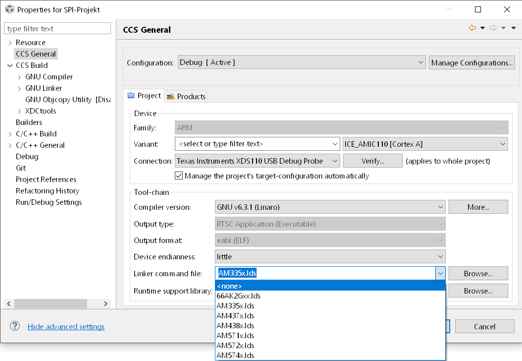
    On further analysis it appears your project contains AM335x.lds which seems to be used in the link step to determine what section gets placed at 0x8000_0000. This file conflicts the following in your .cfg.

    // C-Einstiegspunkt (Startadresse im Speicher)
    
    Program.sectMap[".c_int00"] = new Program.SectionSpec ();
    Program.sectMap[".c_int00"].loadAddress = 0x80000000;

    What is the reason that you are including this file in your project. I compared the file with the default AM335x.lds packaged with CCS and the contents are exactly the same. If you remove the .lds file or exclude it from the build then the entry point is properly placed at 0x8000_0000. 

    There are multiple ways of removing the AM335x.lds file. I am providing some screenshots of ways to do it in CCS.


    After you rebuild the project ensure that he symbol is cinit00 is located at 0x80000000. You can also compare this to the map file from the default Profinet binary to make sure this is aligned.

    Hope this helps.

    Regards,

    Rahul

  • Hi Rahul,

    thank you VERY much! I don’t know why or how we included that file into the project, guess I either copied that from another example or I included it at trying to resolve some linker issue, as checking “AM335x linker command file” sounds right from a user perspective, when you have linker errors and use a AM335x processor. We didn’t know that we must not do that.

  • Glad to know that this is resolved and you can make progress.

    The configuration of the entry point is issue that users have commonly run into hence we have added this as one of the software debug steps here: processors.wiki.ti.com/.../Processor_SDK_RTOS_Boot

    Regards,
    Rahul