This thread has been locked.

If you have a related question, please click the "Ask a related question" button in the top right corner. The newly created question will be automatically linked to this question.

OMAP-L138 IOMUX State

Hi

I am trying to find out the default state of a few pins on the L138 chip upon Power On Reset.

I am looking for the

- POR function of the pin

- Default Input or Output direction of the pin

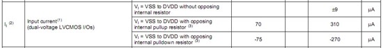
- If that pin has a default internal pullup or pulldown resistor upon exiting reset

When can I can these information

Document SPRS586B does not seem to define these.

  • The default values for the PINMUX registers should be 0x00000000 and is described in the System Reference Guide.  The zero value results in input/high-Z for most pins, but there are a few exceptions such as RTCK, RESETOUT, etc.

    See the Terminal Functions table in the datasheet for non-programmable pull directions.  For programmable pulls, see the PUPD_SEL and PUPD_ENA registers in the System Reference Guide.

  • Hi

    In the case where the POR state of SPI1_SOMI/GP2[11] is = 0, it means that Pin in 3-stated upon POR.

    During this state, I the pin is tri-stated, but the pullup or pulldown is active per the PUPD_ENA & PUPD_SEL POR values.

    SPI1_SOMI/GP2[11] => CP[15] pin group

    If I read the specifications correctly, this pin will be held low through a weak pulldown during reset, and then pulled-up high after reset.

    Where is it documented on the values of the pull-up and pulldowns before and after a device reset?


  • Your understanding of the pin behavior is correct.

    The pull-up and pull-down strengths are in the datasheet under Device Operating Conditions -> Electrical Characteristics Over Recommended Ranges of Supply Voltage... -> (Ii) Input Current with opposing internal pull...

  • Hi

    I am not sure if I understand this specification.

    Assuming a particular pin has a default internal PU condition after POR.

    How much external pulldown resistance do I need to apply to ensure that the line is meeting the Vil levels of the connecting device?

    Thanks in advance for the clarification.

  • To simplify the calculation, you can size the external pull resistor as if you had a voltage divider circuit.

    If you are operating at 3.3V, the equivalent internal pull-up resistance can be simplified as 3.3V / 310uA = 10.6k.  Then it's a matter of picking a pull-down resistor to provide an output voltage below VIL.

    If VIL is 0.8V, you would choose a resistor smaller than about 3.3k so:  3.3V * 3.3k / (3.3k + 10.6k) = 0.78V

  • So for 1.8V, the resistance would be:  1.8V/310uA = 5.8K.  This is a fairly strong pullup resistor.  For a "low" input, the resistor-divider must provide a voltage less than 0.35*1.8V = 0.63V.  To account for noise and all operating temperatures, what is the required margin?  If it's 0.33V, we need a resistor-divider to provide 0.3V.  This works out to ~1.2K.  If this resistor value is required for boot modes for the CPU and bootstraps for other peripherals and the pin is used as an output, the current to oppose the external pulldown is 1.5mA.  For a low-power design, this is a fairly large value.

    Are the current source/sink values for 3.3V and 1.8V, or just 3.3V?

  • Inderjit Bains said:

    So for 1.8V, the resistance would be:  1.8V/310uA = 5.8K.  This is a fairly strong pullup resistor.  For a "low" input, the resistor-divider must provide a voltage less than 0.35*1.8V = 0.63V.  To account for noise and all operating temperatures, what is the required margin?  If it's 0.33V, we need a resistor-divider to provide 0.3V.

    The VIL and pull parameters in the datasheet already comprehend process and temperature variations so you would only need to provide margin for the external resistor and electrical noise on the board.

    Inderjit Bains said:

    Are the current source/sink values for 3.3V and 1.8V, or just 3.3V?

    The source/sink values are for the worst-case 3.3V.  The 1.8V equivalent has not been characterized.

  • Hi

    Are BOOTx function pins during POR have the internal PU/PD enabled? Do we need external resistors to determine the input state of this?


  • Anybody can answer this? 

    Are BOOTx function pins during POR have the internal PU/PD enabled? Do we need external resistors to determine the input state of this?


  • The BOOTx pins are internally pulled down during reset. However using external pull resistors to select the boot mode is still recommended, especially if any of the BOOT pins are routed out.

    Jeff