This thread has been locked.

If you have a related question, please click the "Ask a related question" button in the top right corner. The newly created question will be automatically linked to this question.

CCS/66AK2H14: CCS/66AK2H14

Part Number: 66AK2H14
Other Parts Discussed in Thread: TCI6638K2K, 66AK2H12

Tool/software: Code Composer Studio

Hi ,

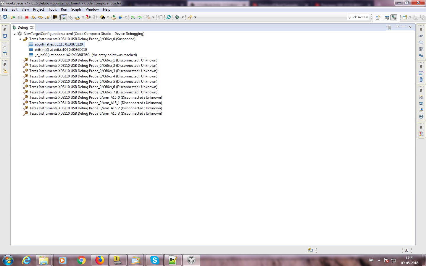
We have designed  customized  board  using 66AK2H14. We are using CCSV7 and TI XDS 110 debug probe to connect board to CCS.

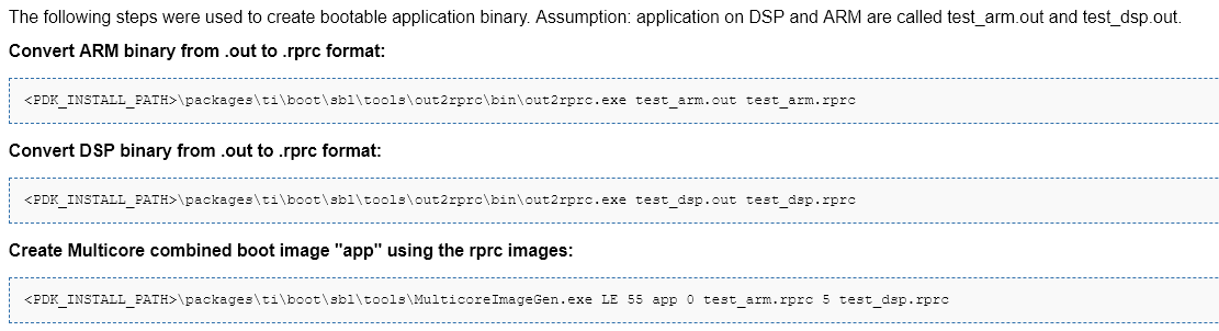
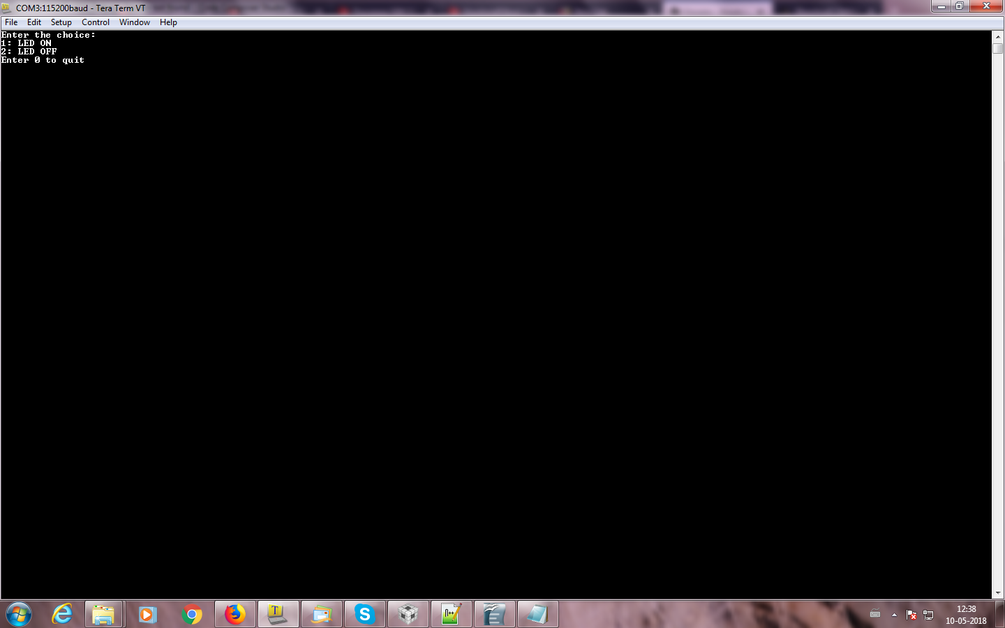
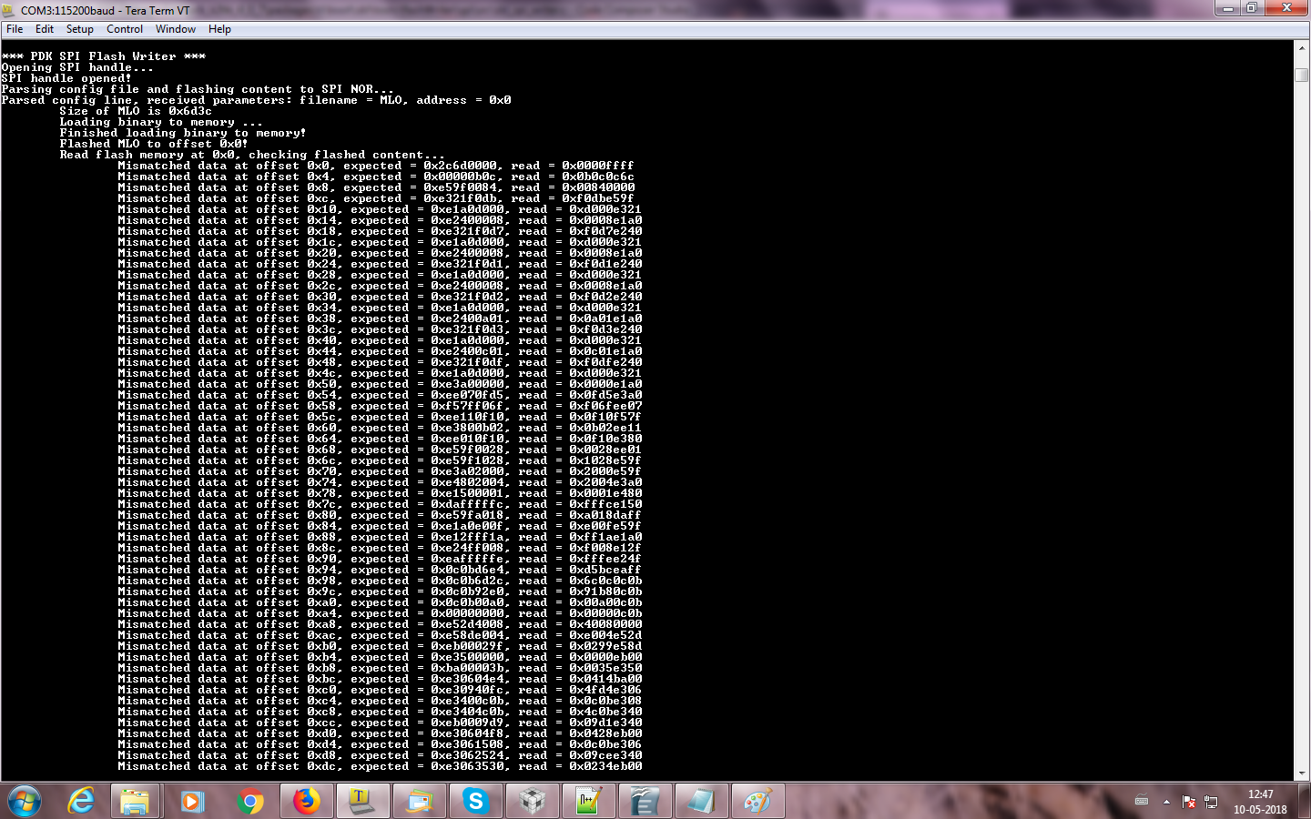
I have to flash gpio_led program into nor flash. I understand I need to convert the .out file to a .dat file so I can write it into NOR flash and run it from there.

I would like to know the procedure that needs to be followed to convert my out file into a dat file. Please provide any suggestions on how I do that.

Thank you,

Mahima Shanbag.

  • Hi,

    See this thread:
    e2e.ti.com/.../1253899

    Best Regards,
    Yordan
  • Hi Yordan,
    Thank you for your quick reply.
    I have gone through that link.
    I was trying to run an application which glows the LED on my boad.It was running successfully and LED's are glowing.
    after that I converted my .out file to .bin using strip6x.exe
    I flashed this .bin file to NOR flash and flashing was successful.
    But when I changed the boot mode to SPI those LED's are not glowing.

    Q1. whether to run the application from NOR flash, image should be in .dat?
    because I downloaded .dat and flashed to NOR that time it was booting.

    Q2. if the image should be in .dat then please tell me how to convert .out to .dat ?

  • Ok, sorry. This thread discusses your query:
    e2e.ti.com/.../389122

    The mentioned tools are located in: ~/ti/pdk_k2e_4_0_9/packages/ti/boot/sbl/tools

    Best Regards,
    Yordan
  • Hi Yorden,

    Thank you for your suggestion,

    I created the .dat file as

    •  B2css.exe gpio_led.hex gpio_led.dat
    • cssAddGphdr.exe -infile gpio_led.dat -outfile gpio_led.dat.gphdr
    • cssAddGptlr .exe -infile gpio_led.dat.gphdr -outfile gpio_led.dat.gphdr.gptlr
    • cp gpio_led.dat.gphdr.gptlr ./bin/gpio_led.dat

    Then I loaded this gpio_led.dat. file to memory at 0x80000000.

    But when I change my boot mode to SPI again LED's are not glowing.

    I am not using ARM. So I set my Boot Master pin of devstat to 1 and I flashed.

    I used board_init function in my program to initialize DDR3,PLL etc

    I attached my application here

    /*
     *  ======== hello.c ========
     *  The hello example serves as a basic sanity check program for SYS/BIOS. It
     *  demonstrates how to print the string "hello world" to stdout. 
     */


    /*
     * Copyright (c) 2014 iWave Systems Technologies Pvt. Ltd.
     *
     * This program is free software; you can redistribute it and/or modify
     * it under the terms of the GNU General Public License version 3
     * as published by the Free Software Foundation.
     *
     * This program is distributed in the hope that it will be useful,
     * but WITHOUT ANY WARRANTY; without even the implied warranty of
     * MERCHANTABILITY or FITNESS FOR A PARTICULAR PURPOSE.  See the
     * GNU General Public License for more details.
     *
     * You should have received a copy of the GNU General Public License
     * along with this program; If not, see <http://www.gnu.org/licenses/>.
     */
    
    /*
     * @file gpio_led_emeni.c
     *
     *
     *
     *
     */
    
    #include <stdio.h>
    #include <stdlib.h>
    #include <hw_types.h>
    //#include <ti/drv/gpio/test/led_blink/src/printf.h>
    #include <ti/board/board.h>
    #include <xdc/std.h>
    
    #include <xdc/runtime/System.h>
    #include <ti/sysbios/BIOS.h>
    #define GPIO29 29
    #define GPIO28 28
    #define GPIO30 30
    #define GPIO31 31
    
    
    #define DIR_REG 0x00000010
    #define OUT_DATA 0x00000014
    #define SET_DATA 0x00000018
    #define CLR_DATA 0x0000001C
    #define IN_DATA 0x00000020
    #define  BASE_ADDR  0X0260BF00 /* GPIO config start address*/
    
    #define ERROR_VAL -1
    #define mask1 0xEFFFFFFF /*gpio28 for setting output*/
    #define mask2 0xDFFFFFFF /*gpio29 for setting output */
    #define mask3 0xBFFFFFFF /*gpio30 for setting output */
    #define mask4 0x7FFFFFFF /*gpio29 for setting output */
    
    #define mask5 0x10000000 /*gpio28 for set_data and clr_data */
    #define mask6 0x20000000 /*gpio29 for set_data and clr_data */
    #define mask7 0x40000000 /*gpio29 for set_data and clr_data */
    #define mask8 0x80000000 /*gpio29 for set_data and clr_data */
    
     /*******************************************************************************
      * Function:    gpio_direction_output
      *
      * Description: This function is used to set particular GPIO pin as output
      *
      * Parameters:  gpio-gpio pin to be setted as direction output
      *
      * Return Value: masked written value
      *
      *****************************************************************************/
    
    void gpio_direction_output(unsigned gpio)
    {
            uint32_t readval;
            uint32_t val1;
            readval=HW_RD_REG32(BASE_ADDR+DIR_REG);
            if(gpio==GPIO28) /* CP's user led1*/
                    val1= readval & mask1;
            else if(gpio==GPIO29) /*CP's user led2 and DP's user led1*/
                    val1= readval & mask2;
            else if(gpio==GPIO30) /* CP's user led3 and DP's user led2*/
                    val1= readval & mask3;
            else if(gpio==GPIO31) /*DP's user led3*/
                    val1= readval & mask4;
             HW_WR_REG32(BASE_ADDR+DIR_REG,val1);
    
    }
    /*******************************************************************************
      * Function:    gpio_set_state
      *
      * Description: This function is used to set particular GPIO pin as 0/1
      *
      * Parameters:  gpio-gpio pin to be set
      *
      * Return Value: masked written value
      *
      *****************************************************************************/
    
    void gpio_set_state(unsigned gpio,int state)
    {
            uint32_t readval;
            uint32_t val1;
            if(gpio==GPIO28)
            {
                    if(state==1)/*set CP's user led1 to high*/
                    {
                            readval=HW_RD_REG32(BASE_ADDR+SET_DATA);
                            val1=readval | mask5;
                            HW_WR_REG32(BASE_ADDR+SET_DATA,val1);
            }
                    else if (state==0) /*set CP's user led1 to low*/
                    {
                            readval=HW_RD_REG32(BASE_ADDR+CLR_DATA);
                            val1=readval | mask5;
                            HW_WR_REG32(BASE_ADDR+CLR_DATA,val1);
                    }
            }
            else if(gpio==GPIO29)
            {
                    if(state==1)  /*set CP's user led2 and DP's user led1 to high*/
                    {
                            readval=HW_RD_REG32(BASE_ADDR+SET_DATA);
                            val1=readval | mask6;
                            HW_WR_REG32(BASE_ADDR+SET_DATA,val1);
                    }
                    else if (state==0)  /*set CP's user led2 and DP's user led1 to low*/
                    {
                            readval=HW_RD_REG32(BASE_ADDR+CLR_DATA);
                            val1=readval | mask6;
                            HW_WR_REG32(BASE_ADDR+CLR_DATA,val1);
                    }
            }
            else if(gpio==GPIO30)
            {
                    if(state==1)   /*set CP's user led3 and DP's user led2 to high*/
                    {
                            readval=HW_RD_REG32(BASE_ADDR+SET_DATA);
                            val1=readval | mask7;
                            HW_WR_REG32(BASE_ADDR+SET_DATA,val1);
                    }
                    else if (state==0)   /*set CP's user led3 and DP's user led2 to low*/
                    {
                            readval=HW_RD_REG32(BASE_ADDR+CLR_DATA);
                            val1=readval | mask7;
                            HW_WR_REG32(BASE_ADDR+CLR_DATA,val1);
                    }
            }
            else if(gpio==GPIO31)
            {
                    if(state==1)  /*set DP's user led3 to high*/
                    {
                            readval=HW_RD_REG32(BASE_ADDR+SET_DATA);
                            val1=readval | mask8;
                            HW_WR_REG32(BASE_ADDR+SET_DATA,val1);
                    }
            else if (state==0)  /*set DP's user led3 to low*/
                    {
                            readval=HW_RD_REG32(BASE_ADDR+CLR_DATA);
                            val1=readval | mask7;
                            HW_WR_REG32(BASE_ADDR+CLR_DATA,val1);
                    }
    
        }
    
    }
    
    /*******************************************************************************
      * Function:    led_init
      *
      * Description: This function is used to initialize GPIO
      *
      * Parameters:  none
      *
      * Return Value: -1--on error
                any integer value-- on success
      *
      *****************************************************************************/
    void led_init(void)
    {
         /*Set direction of GPIO as output*/
        gpio_direction_output(GPIO28); /*SET CP's user led1 as direction output*/
        gpio_direction_output(GPIO29);/*set CP's user led2 and DP's user led1 as direction output*/
        gpio_direction_output(GPIO30);/*set CP's user led3 and DP's user led2 as direction output*/
        gpio_direction_output(GPIO31);/*set DP's user led3 as direction output*/
    }
    /******************************************************************
     Function: main
    *
    ******************************************************************/
    int main(void)
    {
    
        Board_initCfg boardCfg;


            boardCfg = BOARD_INIT_MODULE_CLOCK |
                     BOARD_INIT_PINMUX_CONFIG |
                     BOARD_INIT_DDR |
                     BOARD_INIT_PLL |
                     BOARD_INIT_UNLOCK_MMR  |
                     BOARD_INIT_UART_STDIO;
            Board_init(boardCfg);
            led_init();
            gpio_set_state(GPIO29,1);
    
                 BIOS_exit(0);  /* terminates program and dumps SysMin output */
            return 0;
    }


    Please help to solve this issue.

    I am not understanding what I am missing.

    Q1.Is there any other steps to boot from DSP?

    Q2. whether the problem is with .dat file creation?

    Please help me with this.

    Thank you,

    Mahima Shanbag

  • Hi,
    waiting for your reply..
  • Hi,

    Sorry for missing this. Do you flash the MLO first in spi flash and then your customized binary renamed to app?

    You need the MLO to boot & initialize your SoC and then to load the binary you've created (see the prebuilt images of processor_sdk_rtos_k2hk_4_03_00_05.

    Best Regards,
    Yordan

  • Hi Yordan,

    I tried with pre built images of processor_sdk_rtos_k2hk_4_03_00_05 but it was getting aborted.

    Even I tried  sbl/flash_writer but there also same issue.

    In both the case it was getting aborted at UART_printf.

    I try to rebuild flash writer but I was not able to import it in CCS.

    So Please suggest any alternative method to solve this issue.

    Thank you,

    Mahima Shanbag

  • Hi,

    I've asked the RTOS team to elaborate. They will post their feedback directly here.

    Best Regards,
    Yordan
  • Mahima,

    Please note that K2HK is an ARM master boot device and not a DSP boot master device so the steps for creating .dat file using hex6x don`t directly apply here.

    Technically DSP bootloader is also provide for legacy users but since this is considered a multicore ARM boot device, majority of the use case have been validated with ARM as the boot master. Check the E2E discussion here:

    e2e.ti.com/.../606407

    You need to determine whether you want to boot your application using ROM bootloader or user level secondary bootloader and then determine the approach to create the boot image. Also, you need to start testing the boot on TI EVM before migrating to the custom board which may have different clocks, UART instances and DDR memory.

    Can you answer the following questions so that we can best help you:

    1. Do you want to use direct ROM boot or SDK provided secondary bootloader to boot your application. the currently official supported approach in the RTOS SDK is using Secondary bootloader that is booted by the ROM then sets up DDR, clocks, and loads the application into full SOC address space and then wakes up the slave cores to start executing code. ARM And DSP image can be loaded using this approach into MSMC an/or DDR memory.

    The SBL for K2H SPI NOR is documented here:

    This uses out2rprc and multicoreImageCreate utilities for creating the boot image for SPI.  Attached is the boot log from the system test team for Processor SDK RTOS 4.03 that tested the SBL boot for K2HK platform:


    *** PDK SPI Flash Writer ***
    
    Opening SPI handle...
    
    SPI handle opened!
    
    Parsing config file and flashing content to SPI NOR...
    
    Parsed config line, received parameters: filename = MLO, address = 0x0
    
    	Size of MLO is 0x7200
    
    	Loading binary to memory ...
    
    	Finished loading binary to memory!
    
    	Flashed MLO to offset 0x0!
    
    	Read flash memory at 0x0, checking flashed content...
    
    	Verified flash data equal expected data!
    
    Parsed config line, received parameters: filename = app, address = 0x80000
    
    	Size of app is 0x16e64
    
    	Loading binary to memory ...
    
    	Finished loading binary to memory!
    
    	Flashed app to offset 0x80000!
    
    	Read flash memory at 0x80000, checking flashed content...
    
    	Verified flash data equal expected data!
    
    Successfully flashed memory content!


    **** PDK SBL ****
    
    SBL Revision: 01.00.09.00 (Mar 13 2018 - 18:57:54)
    
    Begin parsing user application
    
    Jumping to user application...


    TMDXEVM6636K2H POST Version 01.00.00.08
    
    ------------------------------------------
    
    SOC Information
    
    BMC Version: 0000
    
    EFUSE MAC ID is: C4 ED BA A0 EB DE 
    
    SA is enabled on this board.
    
    PLL Reset Type Status Register: 0x00000001
    
    Platform init return code: 0x00000000 
    
    Power On Self Test
    
    
    POST running in progress ...
    
    POST I2C EEPROM read test started!
    
    POST I2C EEPROM read test passed!
    
    POST SPI NOR read test started!
    
    POST SPI NOR read test passed!
    
    POST EMIF16 NAND read test started!
    
    POST EMIF16 NAND read test passed!
    
    POST external memory test started!

    2. Can you confirm that when creating the boot image you used the following steps:

    3. Have you tested your bootimage on the TI EVM ? Are you seeing the same issue? If yes, then we can try to reproduce the issue at our end and provide guidance on fixing the issue.

    4. Have you tried the debugging steps provided here:

    processors.wiki.ti.com/.../Processor_SDK_RTOS_Boot

    Regards,

    Rahul

  • Hi Rahul,

    Thank You for your quick response.

    We thought of using DSP as boot master as all our applications are built into DSP. 

    If we use ARM as boot master then how to create .dat  file ,If  steps for creating .dat file using hex6x don`t directly apply.

    Here is the answer for your questions:

    1. we tried with SDK provided secondary bootloader to boot our  application but It was getting aborted as I shared the screen shot above.

        Even we tried with flash writer but faced same issue.

       Then we tried to flash using C:\ti\MCSDK\mcsdk_bios_3_01_03_06\tools\program_evm\binaries by renaming our application as nor.bin and below is the log of that:


    C:\ti\MCSDK\mcsdk_bios_3_01_03_06\tools\program_evm>..\..\..\..\ccsv7\ccs_base\scripting\bin\dss.bat program_evm.js evmk2h-le nor
    board: evmk2h
    endian: Little
    emulation: XDS2xx emulator
    binaries: C:\ti\MCSDK\mcsdk_bios_3_01_03_06\tools\program_evm/binaries/evmk2h/
    ccxml: configs/evmk2h/evmk2h.ccxml
    C66xx_0: GEL Output:
    Connecting Target...

    C66xx_0: GEL Output: TCI6638K2K GEL file Ver is 1.29999995

    C66xx_0: GEL Output: Detected PLL bypass disabled: SECCTL[BYPASS] = 0x00000000

    C66xx_0: GEL Output: (3a) PLLCTL = 0x00000040

    C66xx_0: GEL Output: (3b) PLLCTL = 0x00000040

    C66xx_0: GEL Output: (3c) Delay...

    C66xx_0: GEL Output: (4)PLLM[PLLM] = 0x0000000F

    C66xx_0: GEL Output: MAINPLLCTL0 = 0x070003C0

    C66xx_0: GEL Output: (5) MAINPLLCTL0 = 0x070003C0

    C66xx_0: GEL Output: (5) MAINPLLCTL1 = 0x00000040

    C66xx_0: GEL Output: (6) MAINPLLCTL0 = 0x070003C0

    C66xx_0: GEL Output: (7) SECCTL = 0x00090000

    C66xx_0: GEL Output: (8a) Delay...

    C66xx_0: GEL Output: PLL1_DIV3 = 0x00008002

    C66xx_0: GEL Output: PLL1_DIV4 = 0x00008004

    C66xx_0: GEL Output: PLL1_DIV7 = 0x00000000

    C66xx_0: GEL Output: (8d/e) Delay...

    C66xx_0: GEL Output: (10) Delay...

    C66xx_0: GEL Output: (12) Delay...

    C66xx_0: GEL Output: (13)


    C66xx_0: GEL Output: (13) SECCTL = 0x00090000

    C66xx_0: GEL Output: (Delay...

    C66xx_0: GEL Output: (Delay...

    C66xx_0: GEL Output: (14) PLLCTL = 0x00000041

    C66xx_0: GEL Output: PLL has been configured (CLKIN * PLLM / PLLD / PLLOD = PLLOUT):

    C66xx_0: GEL Output: PLL has been configured (122.879997 MHz * 16 / 1 / 2 = 983.039978 MHz)

    C66xx_0: GEL Output: Power on all PSC modules and DSP domains...

    C66xx_0: GEL Output: Power on all PSC modules and DSP domains... Done.

    C66xx_0: GEL Output: WARNING: SYSCLK is the input to the PA PLL.

    C66xx_0: GEL Output: Completed PA PLL Setup

    C66xx_0: GEL Output: PAPLLCTL0 - before: 0x0x070803C0    after: 0x0x07080400

    C66xx_0: GEL Output: PAPLLCTL1 - before: 0x0x00002040    after: 0x0x00002040

    C66xx_0: GEL Output: DDR begin

    C66xx_0: GEL Output: XMC setup complete.

    C66xx_0: GEL Output: DDR3 PLL (PLL2) Setup ...

    C66xx_0: GEL Output: DDR3 PLL Setup complete, DDR3A clock now running at 666 MHz

    C66xx_0: GEL Output: DDR3A initialization complete

    C66xx_0: GEL Output: DDR3 PLL Setup ...

    C66xx_0: GEL Output: DDR3 PLL Setup complete, DDR3B clock now running at 800MHz.

    C66xx_0: GEL Output: DDR3B initialization complete

    C66xx_0: GEL Output: DDR done

    Writer:C:\ti\MCSDK\mcsdk_bios_3_01_03_06\tools\program_evm/binaries/evmk2h/norwr

    NOR:C:\ti\MCSDK\mcsdk_bios_3_01_03_06\tools\program_evm/binaries/evmk2h/nor.bin

    Start loading nor.bin

    Start programming NOR
    2018_05_10_111742
    NOR Writer Utility Version 01.00.00.03

    Flashing sector 0 (0 bytes of 131072)
    Flashing sector 1 (65536 bytes of 131072)
    Reading and verifying sector 0 (0 bytes of 131072)
    Reading and verifying sector 1 (65536 bytes of 131072)
    NOR programming completed successfully
    End programming NOR

    But When I changed the boot mode to SPI , application was not running from NOR flash.

    2.

    I followed the same steps as u have mentioned like

    out2rprc.exe hello_66AK2H12_C66XX.out gpio_app

    MulticoreImageGen.exe LE 55 app 0 gpio_app


    3.
    Yeah, I have tested it on EVM .

    When I run the Application through JTAG I was getting prints on Tera Term.

    but When I flash it through C:\ti\pdk_k2hk_4_0_7\packages\ti\boot\writer\nor it was flashing successfully , didnt get any prints when I change the boot mode to SPI.

    I try to flash same image with flash_writer utility and I got below log

    4. No I didnt try.

    Please help me with this.

    Regards,

    Mahima Shanbag

  • Mahima,

    you have created an DSP application but have made the error while creating the Multicore boot image. The COREID for the DSP is 5 and you have used 0. Core ID 0 corresponds to A15 core0 hence the bootloader will try to run that code on the A15.

    MulticoreImageGen.exe LE 55 app 5 gpio_app

    I also recommend not mixing SPI writers from mcsdk and Processor SDK. IF you are building the images using Processor SDK RTOS then we recommend that you use the flash writer from the same release as that is what our system test team uses for validation.

    If you want us to reproduce and provide a working bootimage, then I would recommend that you zip your binary and provide it here. Please account for some delays in turn around time because we are helping multiple customers and may take some time to get to this issue on K2H EVM

    Regards,

    Rahul