This thread has been locked.

If you have a related question, please click the "Ask a related question" button in the top right corner. The newly created question will be automatically linked to this question.

UART Rx interrupt not being re-generated


Hello,

I'm running some test/basis code, which simply tries to regenerate a UART Rx interrupt, in response to an incoming Modbus poll message across the wire (8 bytes every 200 msec).  However, I only get one Rx interrupt, then no more, even though the UART registers imply that another interrupt is needed - LSR has the READY bit set, plus IIR indicates a PEND (either RLS or or RDA, depending on the run).  I clear out the event each time, in the UART interrupt, plus read the RBR, so that should set things up for the next interrupt?

extern "C" void hwi_fxn_uart( void )

{

( (evt_reg_1 *)ADDR_EVTCLR1 )->EVTCLR1 = EVT_EF_46;

uint8_t          buf = ( (uart_regs_t *)UART_1 )->RBR;

}

It's a sparse interrupt processing, because I'm simply trying to get to a point that the interrupt is generated each time, before putting in the post-processing.

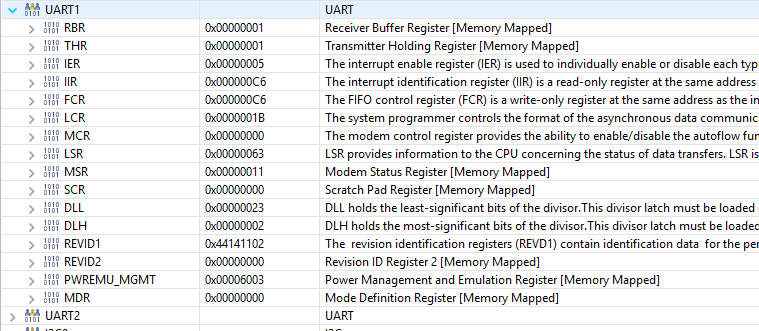
Below is a picture of my UART-related register settings

Any ideas why the interrupt is not being re-generated, would be appreciated.

Regards,

Robert

  • In FIFO mode, I believe you might get only one RX interrupt when
    1) the Rx FIFO reachs the trigger depth
    2) the Rx timesout and there is less than the trigger depth
    On a single Rx interrupt, you may have to read out the FIFO to empty. Or or at least less than trigger depth.
  • Thanks. I had initially been reading all (until LSR DR and OE clear), but went to the single RBR read to debug an issue with the interrupts stopping after some time. That may have been because the GIE was somehow getting cleared after a while, which I found after this post.

    Bad assumption about that single read was that as long as an interrupt was indicated via PEND in IIR, the interrupt would occur ... whether the FIFO was cleared below it's trigger level or not. But per your comments, it won't if the FIFO is not cleared enough each time.

    Now that I've put the complete reads per interrupt again, the UART Rx interrupt is occurring repeatedly again. Now I just have to resolve why the GIE gets cleared after some time, that shuts the UART interrupts down (and all other interrupts). I'm not explicitly clearing it, via HWI_disable(), that I know of ... so bit quizzical. But some re-arrangements of startup-up may have helped already. It's a different issue, either way, so I'd log another thread, if needed.

    Thanks again,
    Robert
  • Alright, I'm back to my original problem.  The UART interrupt continues for sometime, with me now reading all the FIFO each time, then just quits (after 252 iterations).  I've resolved the GIE issue, so it is not disabled

    and the UART registers all say there should be interrupts coming

    Once again, any ideas greatly appreciated.

    Robert

  • A couple thoughts:

    1. Can you add some verification in your ISR that the IIR.IPEND=1 (i.e. no interrupts pending) before you exit?
    2. You have a "character timeout indication" pending.  I think you need to clear that out so that you can get more interrupts.  Are you handling that case in your ISR?  Can you verify per my first suggestion that it is being properly cleared?

  • Not sure if I see the same as Brad but I agree with his suggestions. I think the IIR indicates a pending receiver line status interrupt. The error is receiver overrun. Apparently from not servicing the Rx interrupt.
  • Hi,

    I didn't see these replies until logging a new case here:

    e2e.ti.com/.../686585

    because I'm encountering an INTID of 0 sometimes when coming into the handler.

    Per comments above, I do handle the "character timeout indicator" in my handler, essentially the same as a normal "receive data available" - by reading all the characters until the DR and OE bits are no longer set.

    The actual handler processing is in a Swi, kicked off from the hardware handler. But it doesn't have a case yet for handling this INTID of 0 I'm encountering, since was unexpected and undefined.

    I'll put the IIR.IPEND check in, before exiting, per recommendation.

    Thanks,
    Robert
  • Norman Wong said:
    Not sure if I see the same as Brad but I agree with his suggestions. I think the IIR indicates a pending receiver line status interrupt. The error is receiver overrun. Apparently from not servicing the Rx interrupt.

    Yep, your'e spot on.  INTID=3 (receiver line status).  I was looking at INTID=6, but messed up the fact that bit 0 of IIR is IPEND, not part of INTID.

  • I put in code to not leave the SWI handler until the IPEND is 1, and now I never leave it!

    do
    {
    <process the various cases>

    int_id = ( (uart_regs_t *)UART_1 )->IIR;

    int_id &= UART_IIR_IPEND;

    } while ( int_id == 0U );

  • At the top of my loop is the code below. And in every single case, it's evaluating to 0

    do
    {
    int_id = ( (uart_regs_t *)UART_1 )->IIR;

    int_id &= UART_IIR_INTID;

    int_id >>= UART_IIR_INTID_SHIFT;

    switch ( int_id )
    {
  • Should work. Is uarts_regs_t volatile?
  • All elements of it are

    typedef struct
    {
    volatile uint32_t RBR; // 0x0000
    volatile uint32_t IER; // 0x0004
    volatile uint32_t IIR; // 0x0008
    volatile uint32_t LCR; // 0x000C
    volatile uint32_t MCR; // 0x0010
    volatile uint32_t LSR; // 0x0014
    volatile uint32_t MSR; // 0x0018
    volatile uint32_t SCR; // 0x001C
    volatile uint32_t DLL; // 0x0020
    volatile uint32_t DLH; // 0x0024
    volatile uint32_t REV_ID1; // 0x0028
    volatile uint32_t REV_ID2; // 0x002C
    volatile uint32_t PWREMU_MGMT; // 0x0030
    volatile uint32_t MDR; // 0x0034
    } uart_regs_t;
  • Just curious. You use the structure uart_regs_t to access the UART registers. The IIR (read) and FCR(write) are the same structure member named IIR?

    EDIT: Never mind. You just posted.

  • You might need to volatile the pointer but it should be not be needed. Volatile on the structure member should work. It has worked already on other registers before this IIR problem.
    Some unlikely guesses:
    1) Data cache over UART register range.
    2) Watch window in emulator polling the UART register range.
    3) Coding error, testing IIR bit is altering value rather than just testing.
  • Here's my latest code.  I stripped down to barebones uart handler, and swi function (plus added in volatile).  I get the interrupt for some period of time ... 100-ish or 200-ish, then none.  I've added in the uart registers after.

    For now, just for purposes of trying to get it working, in the Swi, I just read until DR or OE clear, plus the MSR ... since there seems there might be some link into the INTID of 0 I've been seeing, needing to read it.

    I removed the IPEND check, since that just turned it into a polled method, versus int-based (plus it never left the loop monitoring IPEND, as mentioned previously).

    int32_t

    g_cnt_hwi_fxn_uart = 0U;

    #pragma CODE_SECTION( "hwi_fxn" )

    extern "C" void hwi_fxn_uart( void )

    {

    g_cnt_hwi_fxn_uart++;

    ( (volatile evt_reg_1 *)ADDR_EVTCLR1 )->EVTCLR1 = EVT_EF_46;

    Swi_post( SWI_comms );

    }

    uint32_t

       g_cnt_swi_fxn_comms = 0U;

    #define CHECK_IF_UART_RBR_DONE                          ( UART_LSR_DR | UART_LSR_OE )

    extern "C" void swi_fxn_comms( void )

    {

       g_cnt_swi_fxn_comms++;

       uint32_t

           t_0 = 0U;

       uint8_t

           c_buf;

       do

       {

           c_buf = ( (volatile uart_regs_t *)UART_1 )->RBR;

           t_0 = CHECK_IF_UART_RBR_DONE;

           t_0 = ( (volatile uart_regs_t *)UART_1 )->LSR;

           t_0 = ( ( (volatile uart_regs_t *)UART_1 )->LSR & CHECK_IF_UART_RBR_DONE );

       } while ( t_0 != 0U );

       uint16_t

           t_1 = ( (volatile uart_regs_t *)UART_1 )->MSR;

       return;

    }


  • For the code above, I logged both the IIR and LSR everytime coming into both the HWI and SWI, and evertime IIR = 0xC0, and LSR = 0x60. So INTID is 0 every time. LSR indicates only Tx related pending, but I have that interrupt disabled (via IER)

    The last run, both HWI and SWI ran 279 times, then no more (with values above each time)
  • Your last screen capture has IER = 0x0D = 0000 1101, EDSSI = 1, ELSI = 1, TBEI = 0, ERBI = 1. I think EDSSI should be 0. Even though autoflow is not enabled, not sure if any glitch on the flow control pins would cause a flow control interrupt. You should check to see that you are not pinmuxing the flow control pins.

    I would suggest not using the emulator register display as that it itself causes reads of registers. For example using the display window will read the RBR twice in a row. The LSR changes as each RBR. Perhaps try using some more global counters to instrument it and break in and look at the counters when it hangs.

    Any reason why you are using a SWI rather than handling the UART interrupt right away?

    Seems like things went from partially working to not working at all. Maybe time to roll back to partially working.

    You should remove the resolved mark off my post. That might get more eyes on your problem. That's all I got.
  • Norman Wong said:
    Your last screen capture has IER = 0x0D = 0000 1101, EDSSI = 1, ELSI = 1, TBEI = 0, ERBI = 1. I think EDSSI should be 0. Even though autoflow is not enabled, not sure if any glitch on the flow control pins would cause a flow control interrupt. You should check to see that you are not pinmuxing the flow control pins.

    Never had that set, just did in the fog of all this debugging

    Norman Wong said:


    I would suggest not using the emulator register display as that it itself causes reads of registers. For example using the display window will read the RBR twice in a row. The LSR changes as each RBR. Perhaps try using some more global counters to instrument it and break in and look at the counters when it hangs.

    Ok, took out the emulator register display.  There's no real hang, just quits generating an HWI at some random number of iterations.

    Norman Wong said:


    Any reason why you are using a SWI rather than handling the UART interrupt right away?

    Processing will be much more than the bare-bones debug code I'm using now/showed here.  SWI will lift it out of the HWI realm, which is already burdened by other high-intensity HWI processing (McASP-related).

    Norman Wong said:


    Seems like things went from partially working to not working at all. Maybe time to roll back to partially working.

    After the changes above (and before them), I'm still in the 100 to 300 iteration, and no more.  That's about as good/partially working as it's ever been.

    Norman Wong said:


    You should remove the resolved mark off my post. That might get more eyes on your problem.

    Not sure how to do that!

    Norman Wong said:

    That's all I got.

    Appreciate your continued help.  Not an easy one.
    Robert
  • You should be able to go back to my green bordered resolved post and click on some button to the effect of "Unresolve". Only the original poster gets those button and I am not sure what they look like anymore. There might more buttons hiding under the "More" button. The interface has changed over the years.

    Forum Moderators, please unresolve my post.

    It would seem that threads get automatically locked if there is no activity for 24-hours. Once locked, you cannot post to it? Have no idea why TI implemented these lock rules. It was not like this before.

    The BIOSPSP 3 UART driver handles the interrupts directly in the handler. They appear to call a Swi_post() to trigger a tasklet. On the C6748, an SWI sometimes maps to the highest priority NMI. I assume that with BIOSPSP is it not. If you are using BIOSPSP, any reason why you don't use their UART driver?
  • Norman Wong said:
    You should check to see that you are not pinmuxing the flow control pins.

    A quick follow up about this.  The flow control I think you're referring to are UART1_RTS and UART1_CTS.  I was multiplexing both of those to the McASP (AHCLKR on the UART1_RTS pin, and AHCLKX on the UART1_CTS pin).  In reality, for my target hardware, only AHCLKX is being used, to drive the MCLK on a codec.  The AHCLKR/UART1_RTS pin is a no-connect on my board.  So I removed it from the pin-mux.  AHCLKX/UART1_CTS needs to be remained mux'd to to McASP.

    Does this make sense, and is it cause for concern?

    Regards,

    Robert

  • Norman Wong said:
    You should be able to go back to my green bordered resolved post and click on some button to the effect of "Unresolve".

    Only the original poster gets those button and I am not sure what they look like anymore. There might more buttons hiding under the "More" button. The interface has changed over the years.

    Looked for that, but only found "flag as spam/abuse"
     

    Norman Wong said:

    The BIOSPSP 3 UART driver handles the interrupts directly in the handler. They appear to call a Swi_post() to trigger a tasklet. On the C6748, an SWI sometimes maps to the highest priority NMI. I assume that with BIOSPSP is it not. If you are using BIOSPSP, any reason why you don't use their UART driver?

    I'm using SYS-BIOS, but not BIOSPSP, as far as I know.  Just created the interrupt in the bios .cfg like this

    var hwi_8_params = new Hwi.Params();
    hwi_8_params.instance.name = "hwi_name_uart";
    hwi_8_params.arg = 0
    Program.global.hwi_uart = Hwi.create( 8, "&hwi_fxn_uart", hwi_8_params );

    then wrote my own handler (modeled after many I've been doing on the C67XX family over the years, etc). It shouldn't be that hard.  But I might look into the BIOSPSP for additional driver work.

    Robert

  • A little too much time on my hands. Here's some code that should illustrate some if the concepts in this thread.

    uint32_t g_cnt_hwi_fxn_uart = 0U;
    uint32_t g_cnt_swi_fxn_comms = 0U;
    uint32_t g_cnt_bi = 0U;
    uint32_t g_cnt_fe = 0U;
    uint32_t g_cnt_pe = 0U;
    uint32_t g_cnt_oe = 0U;
    
    static "C" void uart_rx_isr(volatile uart_regs_t *reg)
    {
      uint32_t rbr;
    
      for(;;)
      {
        lsr = reg->LSR; // Read ONCE!
    
        if (lsr & UAR_LSR_OE) g_cnt_oe++;
    
        if ((lsr & UART_LSR_DR)==0) break;
    
        rbr = reg->RBR;
    
        // Above code will write to the UART and cause changes to the
        // LSR. A memory barrier may be required here if the writes have
        // not cleared the instruction pipeline or cache before LSR is read
        // again. Maybe the code below is enough to flush the pipeline.
    
        // Test for errors associated with this byte.
        if (lsr & UAR_LSR_BI) g_cnt_bi++;
        if (lsr & UAR_LSR_FE) g_cnt_fe++;
        if (lsr & UAR_LSR_PE) g_cnt_pe++;
    
        // Save rbr for main line if no errors bi, fe, or pe
      }
    }
    
    extern "C" void hwi_fxn_uart( void )
    {
      volatile uart_regs_t *reg = (volatile uart_regs_t *)UART_1;
    
      uint32_t iir;
      uint32_t intid;
      uint32_t dummy;
      int      limit = 8; // Should be at most 5 INTIDs
    
    
      g_cnt_hwi_fxn_uart++;
    
      // Clear DSPINTC event for UART1
      ((volatile evt_reg_1 *)ADDR_EVTCLR1 )->EVTCLR1 = EVT_EF_46;
    
      g_cnt_swi_fxn_comms++;
    
      do
      {
        iir = reg->IIR;
        if (iir & UART_IIR_IPEND) break;
    
        intid   = iir;
        intid  &= UART_IIR_INTID;
        intid >>= UART_IIR_INTID_SHIFT;
        switch(intid)
        {
          case UART_IIR_INTID_MS:
            dummy = reg->MSR;
            break;
          case UART_IIR_INTID_THRE:
            reg->IER &= ~ETBEI; // Nothing to send
            break;
          case UART_IIR_INTID_RDA:
          case UART_IIR_INTID_CTI:
          case UART_IIR_INTID_RLS:
            uart_rx_isr(reg);
            break;
          default:
            break;
        }
        // Above code will write to the UART and cause changes to the
        // IIR. A memory barrier may be required here if the writes have
        // not cleared the instruction pipeline or cache before the IIR.
        // is read again.
      }
      while(--limit);
    }


    I've shown the UART processing being handled in the ISR. With a SWI, I assume the UART processing is in main line code. I am not sure you can afford to wait that long. Especially at fast baud rates.

  • This line
    ((volatile evt_reg_1 *)ADDR_EVTCLR1 )->EVTCLR1 = EVT_EF_46;
    works if EVT_EF_46 has the value 46-32 or 14.

    EDIT: Make that EVT_EF_46 = 1<<14.

  • Have not completely caught up with this thread and also trying to connect the dots between this post and the INITID 0 post from Robert.

    i see some pinmux discussion here on UART and McASP - I dont know if it is in mix, but did want to highlight the note that is there in the TRM at the beginning of pinmux registers

    Pin Multiplexing Control Registers (PINMUX0-PINMUX19)

    Extensive use of pin multiplexing is used to accommodate the large number of peripheral functions in the smallest possible package. On the device, pin multiplexing can be controlled on a pin by pin basis. This is done by the pin multiplexing registers (PINMUX0-PINMUX19). Each pin that is multiplexed with several different functions has a corresponding 4-bit field in PINMUXn. Pin multiplexing selects which of several peripheral pin functions control the pins I/O buffer output data and output enable values only. Note that the input from each pin is always routed to all of the peripherals that share the pin; the PINMUX registers have no effect on input from a pin. Hardware does not attempt to ensure that the proper pin multiplexing is selected for the peripherals or that interface mode is being used

  • Mukul Bhatnagar said:

    Have not completely caught up with this thread and also trying to connect the dots between this post and the INITID 0 post from Robert.

    We could close out the other INTID 0 post, if this one could be marked as unresolved ... since this one is the catch-all for the problem now.

    Mukul Bhatnagar said:

    Pin multiplexing selects which of several peripheral pin functions control the pins I/O buffer output data and output enable values only. Note that the input from each pin is always routed to all of the peripherals that share the pin; 

    As mentioned earlier in this thread, the signals/pins being considered are UART1_CTS and UART1_RTS, which I guess are the flow-control.  They are shared with the AHCLKX and AHCLKR signals.  For my application, pinmux was setup to connect AHCLKX and AHCLKR.  Only AHCLKX is really needed, since it's driving a codec input clock.  I had just pinmuxed AHCLKR at the same time.  I can leave it unpinmuxed, or put it to UART1_RTS. 
    However, neither UART1_RTS or UART1_CTS are used on my target board at all.
    I don't feel this is the source of my problems, as described in this thread, but I have to consider all and anything.
    Robert
  • Norman Wong said:

    This line
    ((volatile evt_reg_1 *)ADDR_EVTCLR1 )->EVTCLR1 = EVT_EF_46;
    works if EVT_EF_46 has the value 46-32 or 14.

    EDIT: Make that EVT_EF_46 = 1<<14.

    That's what I've been doing in my application as well ( 1 << 14 ).  Thanks for the psuedo-code.  

    Robert

  • That one sentence regarding inputs being always connected together that Mukul pointed out is somewhat disturbing to me. That means some bad side-effects if you are expecting a unmuxed peripheral pins to be disconnected from the outside world. In this case:

    Pin A2
    - PRU0_R31[18] - Input
    - AHCLKR - Input/Output- In this case muxed but unused
    - PRU0_R30[18] - Output
    - UART1_RTS - Output
    - GP0[11] - Input/Output

    Pin A3
    - PRU0_R31[17] - Input
    - AHCLKX - Input/Output - In this case used as output to codec clock
    - USB_REFCLKIN - Input
    - UART1_CTS - Input
    - GP0[10] - Input/Output

    So that means the signal out on AHCLKX can be seen as input on PRU0_R31[17], USB_REFCLKIN, UART1_CTS, and GP0[10] (assuming this is configured as an input). In this case, in theory, UART1_CTS should be toggling in tune with the AHCLKX clock.

    If GP0[10] was configured as an output, that would mean there was two outputs tied together. Very bad.
  • Norman Wong said:
    Pin A3
    - PRU0_R31[17] - Input
    - AHCLKX - Input/Output - In this case used as output to codec clock
    - USB_REFCLKIN - Input
    - UART1_CTS - Input
    - GP0[10] - Input/Output

    So that means the signal out on AHCLKX can be seen as input on PRU0_R31[17], USB_REFCLKIN, UART1_CTS, and GP0[10] (assuming this is configured as an input). In this case, in theory, UART1_CTS should be toggling in tune with the AHCLKX clock.

    If GP0[10] was configured as an output, that would mean there was two outputs tied together. Very bad.

    No, that's not what it means.

    If you configure Pin A3 as GP0[10], then that means PRU0_R31[17] (an input) will be able to "see" whatever is on the pin.  And related to this case, it also means the UART1_CTS pin (an input) of the UART will "see" what's on the pin.  So it is important that you configure flow control as disabled, because it would still be impacted by what's on the pin.

  • I wasn't clearing out the MCR, flow control registers (AFE, RTS), but MCR was always 0 anyways.  I've put in explicit clears of those bits now, as part of start-up configuration.

    I got rid of the SWI, and am doing everything in the uart handler, and am getting further.  This code below appears to be running without stop, i.e. the interrupts are being constantly generated.

    uint32_t

    g_cnt_hwi_fxn_uart = 0U;

    #pragma CODE_SECTION( "hwi_fxn" )
    extern "C" void hwi_fxn_uart( void )
    {
    g_cnt_hwi_fxn_uart++;

    uint16_t

    t_0 = 0U;

    uint8_t
    c_buf;

    do
    {
    c_buf = ( (volatile uart_regs_t *)UART_1 )->RBR;

    t_0 = CHECK_IF_UART_RBR_DONE;

    t_0 = ( (volatile uart_regs_t *)UART_1 )->LSR;

    t_0 = ( ( (volatile uart_regs_t *)UART_1 )->LSR & CHECK_IF_UART_RBR_DONE );

    } while ( t_0 != 0U );

    }

    Robert

    P.S.  Is there a better way to cut and paste code here?, all the tabs and formatting gets lost ... makes for hard reading

  • That's good you have something that's working now. It might be worth testing it overnight so we can be sure. Also, you should be leveraging the IIR register within the interrupt. Can you add some additional code to check that register?
  • Brad Griffis said:
    Also, you should be leveraging the IIR register within the interrupt. Can you add some additional code to check that register?

    I originally had, but pared everything back to bare-bones, for debugging.  I'll start to add the IIR check/handling, if this holds up.
    I wonder what the problem is with using an SWI, but will worry about that later.
    Robert
  • Brad Griffis said:

    No, that's not what it means.

    If you configure Pin A3 as GP0[10], then that means PRU0_R31[17] (an input) will be able to "see" whatever is on the pin.  And related to this case, it also means the UART1_CTS pin (an input) of the UART will "see" what's on the pin.  So it is important that you configure flow control as disabled, because it would still be impacted by what's on the pin.

    Okay. I think I understand. The statement

    "the input from each pin is always routed to all of the peripherals that share the pin"

    might need to be qualified that the pin is always routed to "input only" peripheral pins. Pins that are bidirectional be under mux control.

    EDIT: Fix errors.

  • Robert56682 said:

    P.S.  Is there a better way to cut and paste code here?, all the tabs and formatting gets lost ... makes for hard reading

    - Click on the red button "Reply",
    - Then "Insert Code, Attach Files and more..."
    - On the tool bar there is an icon that with "</>". Hover text says "Syntaxhighlighter"
    - Click in the composition text window to establish the insert point.
    - Click on the "</>". Pops up another window. In that window, you can paste your code. Close the window.
    - The inserted code will appear as normal text in your compose window. It will appear in "code style" when posted. I thought there used to be a "preview" button but I don't see it anymore.

  • uint16_t t_0 = 0U;
    uint8_t  c_buf;
    do
    {
      c_buf = ( (volatile uart_regs_t *)UART_1 )->RBR;
      t_0 = CHECK_IF_UART_RBR_DONE;
      t_0 = ( (volatile uart_regs_t *)UART_1 )->LSR;
      t_0 = ( ( (volatile uart_regs_t *)UART_1 )->LSR & CHECK_IF_UART_RBR_DONE );
    } while ( t_0 != 0U );

    Comments:

    - The line "t_0 = CHECK_IF_UART_RBR_DONE" doesn't seem to do anything.
    - LSR is read twice. The error bits in LSR get cleared on LSR read. You will lose track of errors.
    - RBR is read before LSR. The LSR error bits for the first byte are lost.
    - RBR is read before LSR. If there is nothing in RBR, UART behavor is undefined.

    The last comment could happen. With a SWI, you couild get a HWI wil you are running the SWI. The SWI runs again but the previous SWI has already drained the FIFO. The SWI reads the RBR and nothing is there. Might result is an error condition.

  • uint32_t
    	g_cnt_hwi_fxn_uart = 0U;
    
    #define UART_IIR_INTID_MASK					( UART_IIR_INTID_THRE | UART_IIR_INTID_RDA | UART_IIR_INTID_RLS | UART_IIR_INTID_CTI )
    
    #define MAX_HWI_FXN_UART					8U
    
    #pragma CODE_SECTION( "hwi_fxn" )
    extern "C" void hwi_fxn_uart( void )
    {
    	g_cnt_hwi_fxn_uart++;
    
        uint8_t
            c_buf;
    
    	uint8_t
    		cnt_0 = 0U;
    				
    	uint16_t
    		tmp_0 = ( (volatile uart_regs_t *)UART_1 )->MSR;
    
        do
        {
    		uint16_t
    			iir = ( (volatile uart_regs_t *)UART_1 )->IIR;
    
    		if ( iir & UART_IIR_IPEND )
    		{
    			break;
    		}
    
    		uint16_t
    			int_id = ( iir & UART_IIR_INTID );
    
    		int_id >>= UART_IIR_INTID_SHIFT;
    
    		switch( int_id )
    		{
    			case UART_IIR_INTID_MODSTAT:
    
    				tmp_0 = ( (volatile uart_regs_t *)UART_1 )->MSR;
    
    				break;
    
    			case UART_IIR_INTID_THRE:
    				
    				( (volatile uart_regs_t *)UART_1 )->IER &= ~UART_LSR_THRE;
    
    				break;
    
    			case UART_IIR_INTID_RDA:
    			case UART_IIR_INTID_CTI:
    			case UART_IIR_INTID_RLS:
    
            		c_buf = ( (volatile uart_regs_t *)UART_1 )->RBR;
    
    				break;
    
    			default:
    				break;
    		}
    
    		cnt_0++;
    
        } while ( cnt_0 != MAX_HWI_FXN_UART );
    				
    }

  • I've updated to the above, which is essentially what you had provided the other day.  It appears to be working, with logging of "c_buf" showing the expected modbus probe, and cnt_0 always a value of 1.  I'm cautiously optimistic that I can move forward now, with this as a basis.  I'll probably still examine the SWI angle, but maybe more on a collected buffer of data, not byte-by-byte.

    Thanks much Norman/all,

    Robert

    P.S.  Inserting the code applied the same formatting to any associated response text like this, which then ran off the end of the text box window, etc.  So I ended up breaking the code/text into two different posts.

  • Norman Wong said:
        if (lsr & UAR_LSR_OE) g_cnt_oe++;


    Quick follow-up ... don't you still want to read the character, in the OE case?

    Robert

  • Well... I do read "a" character a few lines after that line. The OE does not apply to a specific character. It applies to entire FIFO and it clears upon reading the LSR. So in that LSR.DR loop, the OE bit should be seen once on the first LSR read. The test could moved outside the loop for a quicker tighter loop at expense of more complicated code flow.
  • Apologies, you break on the DR == 0, not OE (so character does get read). Ok, will keep that optimization in mind, if ever felt needed.

  • Now that I'm moving on in my design, a wish list would be to know the timing between each character input to the UART, but without having to interrupt on every one. This would allow implementation of the comms protocol with significantly lower overhead. But, per understandings, UARTs don't reporting delta time between each character.
  • Not quite understanding. For modbus, it is usually a message of back to back bytes. Meaning the delta between bytes would be zero. You could use a system tick counter to time between UART interrupts or messages. An automatic delta time is in the realm of FPGAs with custom IPs.
  • Robert56682 said:
    uint32_t
    	g_cnt_hwi_fxn_uart = 0U;
    
    #define UART_IIR_INTID_MASK					( UART_IIR_INTID_THRE | UART_IIR_INTID_RDA | UART_IIR_INTID_RLS | UART_IIR_INTID_CTI )
    
    #define MAX_HWI_FXN_UART					8U
    
    #pragma CODE_SECTION( "hwi_fxn" )
    extern "C" void hwi_fxn_uart( void )
    {
    	g_cnt_hwi_fxn_uart++;
    
        uint8_t
            c_buf;
    
    	uint8_t
    		cnt_0 = 0U;
    				
    	uint16_t
    		tmp_0 = ( (volatile uart_regs_t *)UART_1 )->MSR;
    
        do
        {
    		uint16_t
    			iir = ( (volatile uart_regs_t *)UART_1 )->IIR;
    
    		if ( iir & UART_IIR_IPEND )
    		{
    			break;
    		}
    
    		uint16_t
    			int_id = ( iir & UART_IIR_INTID );
    
    		int_id >>= UART_IIR_INTID_SHIFT;
    
    		switch( int_id )
    		{
    			case UART_IIR_INTID_MODSTAT:
    
    				tmp_0 = ( (volatile uart_regs_t *)UART_1 )->MSR;
    
    				break;
    
    			case UART_IIR_INTID_THRE:
    				
    				( (volatile uart_regs_t *)UART_1 )->IER &= ~UART_LSR_THRE;
    
    				break;
    
    			case UART_IIR_INTID_RDA:
    			case UART_IIR_INTID_CTI:
    			case UART_IIR_INTID_RLS:
    
            		c_buf = ( (volatile uart_regs_t *)UART_1 )->RBR;
    
    				break;
    
    			default:
    				break;
    		}
    
    		cnt_0++;
    
        } while ( cnt_0 != MAX_HWI_FXN_UART );
    				
    }

    I think you should log an error in the case that you exit due to MAX_HWI_FXN_UART.  One thought that comes to mind is to swap the two pieces of code that I've highlighted (though I think their polarities also need to flip). That way you could call Log_printf or a function of your choosing prior to the "break" statement.

  • Norman Wong said:
    Not quite understanding. For modbus, it is usually a message of back to back bytes. Meaning the delta between bytes would be zero. You could use a system tick counter to time between UART interrupts or messages. An automatic delta time is in the realm of FPGAs with custom IPs.

    Yeah, thought so (beyond UART capability).  Reason is trying to take advantage of the FIFO, i.e. interrupt after 4, 8 or 14 bytes, instead of the byte-by-byte interrupt overhead.  In that case, the delta timing between bytes would be needed to distinguish packet boundaries, i.e. if I knew the delta was the poll/modbus rate between packets, I could parse and respond accordingly. 

    Robert

  • #pragma CODE_SECTION( "hwi_fxn" )
    extern "C" void hwi_fxn_uart( void )
    {
    	g_cnt_hwi_fxn_uart++;
    
        uint8_t
            c_buf;
    
    	uint8_t
    		cnt_0 = ZERO_U;
    				
    	uint16_t
    		cnt_1 = ZERO_U;
    
    	uint16_t
    		tmp_0;
    
    	uint16_t
    		t_0;
    
    	((volatile evt_reg_1 *)ADDR_EVTCLR1 )->EVTCLR1 = EVT_EF_46;
    
    	uint16_t
    		iir = ( (volatile uart_regs_t *)UART_1 )->IIR;
    
    	while ( !CHK_BIT( iir, UART_IIR_IPEND ) )
        {
    		uint16_t
    			int_id = ( iir & UART_IIR_INTID );
    
    		int_id >>= UART_IIR_INTID_SHIFT;
    
    		switch( int_id )
    		{
    			case UART_IIR_INTID_MODSTAT:
    
    				tmp_0 = ( (volatile uart_regs_t *)UART_1 )->MSR;
    
    				break;
    
    			case UART_IIR_INTID_THRE:
    				
    				( (volatile uart_regs_t *)UART_1 )->IER &= ~UART_LSR_THRE;
    
    				break;
    
    			case UART_IIR_INTID_RDA:
    			case UART_IIR_INTID_CTI:
    			case UART_IIR_INTID_RLS:
    
    				cnt_1 = ZERO_U;
    				
    				for ( ; ; )
    				{
    					cnt_1++;
    
    					uint16_t
    						lsr = ( (volatile uart_regs_t *)UART_1 )->LSR;
    
    					if ( !CHK_BIT( lsr, UART_LSR_DR ) )
    					{
    						break;
    					}
    					
    					c_buf = ( (volatile uart_regs_t *)UART_1 )->RBR;
    				}
    
    				break;
    
    			default:
    				break;
    		}
    
    		cnt_0++;
        	
    		if ( cnt_0 == MAX_HWI_FXN_UART )
    		{
    			break;
    		}
    
    		iir = ( (volatile uart_regs_t *)UART_1 )->IIR;
        }
    }

  • There's my latest, which seems to be holding up well so far. It's a combo of things, including Norman's code and your suggestion about swapping the statements, to allow logging when exceeding MAX_HWI_FXN_UART (logging would go where the break statement is).

    Robert

  • Just a follow-up, I've tried to run this overnight, but in the morning, I can see the target has reverted back to the code in flash, not what I'm running under emulation. However, there have been many changes since I last did overnight runs, including this change, and a complete SYS-BIOS and tools update, so it could be any of those things.

    I'm re-running with a breakpoint at main, to try and catch and re-start, but I'm guessing whatever took it to flash code will take out the emulation, so I'll never hit that breakpoint.

    Robert

  • Maybe a power bump? Any VCRs blinking 12:00? Ueah...what's a VCR. Maybe a watchdog timer?
  • Norman Wong said:
    Maybe a power bump? Any VCRs blinking 12:00? Ueah...what's a VCR. Maybe a watchdog timer?

    Ha, I had one of those things.  

    I don't think power bump, but good call on a possible watchdog reset :)  It appears that I may have had one, that inadvertently got called.  I'll fix/disable it, and see.  Hopefully that's it.

    Thanks,

    Robert

  • I ran overnight, and it didn't appear to go to flash code this time (helps to avoid inadvertent watchdogs). But the Uart handler was no longer occurring. But I'm pretty sure that's because the Modbus strobe stopped over-night, from the application generating it. When I restarted that application, Uart breakpoints occurred again.

    I'll run with that, and start piecing together the byte-by-byte Modscan handler again. Not a comms fan, so hopefully done with this soon!
  • Good to hear.