This thread has been locked.

If you have a related question, please click the "Ask a related question" button in the top right corner. The newly created question will be automatically linked to this question.

RTOS/AM5726: Custom board pinmux

Part Number: AM5726

Tool/software: TI-RTOS

Hello everybody ,

please I m working with TIRTOS  on AM5726 IDK . 

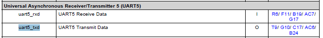
now I want to take out few signals ( like an extra UART etc ) so  I  modified  using PINMUX utilty some pins  starting from original pimux. 

I started from  idkAM572x_SR2.0.pinmux  made modification and then took   *.h  and *.c  files and replacd the original one in 

C:\ti\pdk_am57xx_1_0_9\packages\ti\board\src\idkAM572x.    is this enough  ?    reason I am asking is when I debug  ( like Board_init function)  debugger tells some source  files are missing ...

so I searched FAQ and found on http://processors.wiki.ti.com/index.php/Pin_Mux_Utility_for_ARM_MPU_Processors#Output_File_Formats

that   you need "to rebuild the PDK as per  here After updating the files in the directories below you will need to recompile the board_lib and sbl components of the Processor SDK Platform Development Kit (PDK). Follow this guide on Rebuilding The PDK "     : is this the right procedure ? 

please coudl you confirm me proper  sequence  to avoid any issue ?  in the future I ll start from  IDK pinmux for changig pinmux to my custom board 

thank you very much 

regards

Carlo

  • The RTOS team have been notified. They will respond here.
  • Carlo,

    Refer to Section 9 of the Application development with Processor SDK RTOS to see all top level steps of chnaging clocking, DDR and pinmux. After any change in the code, it is required to rebuild the board library for the change to take effect.

    To summarize, I am listing all steps related changes to pinmux using board library.

    • Use pinmux tool to import existing configuration or create new configuration.
    • Update existing files:
      • After changes are done, download the files: boardPadDelayTune.h, boardPadDelayInit.c, boardPadDelayDevice.c and boardPadDelay.h
      • Replace the files in the board library linked to application. In your case it would be pdk_am57xx_1_0_xx\packages\ti\board\src\idkAM572x
    • Other peripheral changes: UART/I2C/GPIO/MCSPI instances in board_cfg.h file if there are any changes
    • Rebuild the board_lib for the changes to be built as part of the board library linked.
    • Rebuild the application/boootloader or any other code that calls the Board_Init API which calls into the board library.

    When you run the application the updated pinmuxing should reflect in the CTRL_CORE_PAD registers.

    Regards,

    Rahul

  • HI Rahul ,

    some confirmations/questions  out of your  suggestions :

    • After changes are done, download the files: boardPadDelayTune.h, boardPadDelayInit.c, boardPadDelayDevice.c and boardPadDelay.h

     Replace the files in the board library linked to application. In your case it would be pdk_am57xx_1_0_xx\packages\ti\board\src\idkAM572x

    -->   CC : This was done by me. OK

    • Other peripheral changes: UART/I2C/GPIO/MCSPI instances in board_cfg.h file if there are any changes

    Rebuild the board_lib for the changes to be built as part of the board library linked.

                      -- >      CC : Are the following instructions OK?

                                  C:\ti\pdk_am57xx_1_0_9\packages\pdksetupenv.bat

    •                             C:\ti\pdk_am57xx_1_0_9\packages\gmake LIMIT_BOARDS="idkAM572x"

    • Rebuild the application/boootloader or any other code that calls the Board_Init API which calls into the board library.

                     --> CC:    So basically a standard compilation of my test project, right?

    When you run the application the updated pinmuxing should reflect in the CTRL_CORE_PAD registers.

                     --> CC : I will read the following registers in order to verify, is that correct?

                          // read CTRL_CORE_PAD_SPI2_D0 for UART5_RXD selection

                           retVal = *(uint32_t *)0x4A0037C8;

                          // read CTRL_CORE_PAD_SPI2_CS0 for UART5_TXD selection

                         retVal = *(uint32_t *)0x4A0037CC;

    thank you

    regards

    Carlo

  • Colombo Carlo said:

                      -- >      CC : Are the following instructions OK?

                                  C:\ti\pdk_am57xx_1_0_9\packages\pdksetupenv.bat

    •                             C:\ti\pdk_am57xx_1_0_9\packages\gmake LIMIT_BOARDS="idkAM572x"

    The above step will build the whole PDK package and all its components which can be time consuming. To update just the board library after you setup the environment, you can use :

    C:\ti\pdk_am57xx_1_0_9\packages\gmake board_lib LIMIT_BOARDS="idkAM572x"

    Additional build time can be improved using core specific build. If you want ot rebuild the board_lib only for A15 core, you can use :

    C:\ti\pdk_am57xx_1_0_9\packages\gmake board_lib LIMIT_BOARDS="idkAM572x"  LIMIT_CORES="a15_0"

    Refer Examples in the article :http://processors.wiki.ti.com/index.php/Rebuilding_The_PDK#Building_PDK_using_gmake_in_Windows_environment 

    --> CC : I will read the following registers in order to verify, is that correct?

                          // read CTRL_CORE_PAD_SPI2_D0 for UART5_RXD selection

                           retVal = *(uint32_t *)0x4A0037C8;

                          // read CTRL_CORE_PAD_SPI2_CS0 for UART5_TXD selection

                         retVal = *(uint32_t *)0x4A0037CC;

  • Hi Rahul ,
    thank you very much
    please could you confirm my last question ? :
    --> CC : I will read the following registers in order to verify, is that correct?

    // read CTRL_CORE_PAD_SPI2_D0 for UART5_RXD selection

    retVal = *(uint32_t *)0x4A0037C8;

    // read CTRL_CORE_PAD_SPI2_CS0 for UART5_TXD selection

    retVal = *(uint32_t *)0x4A0037CC;

    best regards
    Carlo
  • Carlo,

    I had replied to that question but  the response was truncated when I posted it. I am posting that response again.

    The UART5_RXD and UART5_TXD pins are multiplexed on different balls on the AM57x package as you can see from the datasheet.

    If the customer is using G17 and B24 pins on the package for UART5 functionality then those are the correct register to check for confirming the mux mode.

    Regards,

    Rahul

  • Hi Rahul

    thank you very much  It worked  !

    just a suggestion to other users  ,   when using  a new peripherals remember to enable clocks  :  I did not in first  try and  it took me sometimes

    regards

    Carlo