This thread has been locked.

If you have a related question, please click the "Ask a related question" button in the top right corner. The newly created question will be automatically linked to this question.

the program executes abnormally after DSP power up

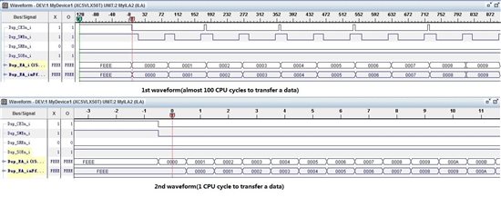
Hi, everyone. In my board, DSP(6455) transfers data from L2 RAM to external memory with EDMA3. After power up, I found DSP run normally(EDMA3 has low efficiency, it uses almost 80 CPU cycles to transfer a data) with its first loaded program. But if the program reloaded(.out file not changed) or restarted, DSP could run normally(EDMA3 transfer a data in one CPU cycle). what is the reason? 

  • Hi Gang,

    are you initializing the DDR2 interface in your code or is it done in a GEL-File?

    Regarding the EDMA3 performance there's a good appnote.

    Please see http://www.ti.com/litv/pdf/spraag8

    Kind regards,

    one and zero

  • one and zero said:

    Hi Gang,

    are you initializing the DDR2 interface in your code or is it done in a GEL-File?

    Hi, one and zero. I don't intialize the DDR2 interface of DSP in my code nor it is initialized in a GEL-File. I have seen the appnote and I think this problem has little relation with the appnote. I think DSP only moves its PC point back to init_00 after reload or restart the program. Why there is difference between the first load and the reload(or restart)? Or if there is something I have not consided about. About this problem, I have asked in another post, you said its the power-up problem. But we have verified all your suggestions and we are sure that the power-up requirement follows the data sheet.

    Thanks again. 

  • Hi Gang,

    if you do not initialize the DDR2 interface how can you move data there?

    Restart only puts the PC back to your entry point which is c_int00. What happens in addition to that depends if you have a GEL-file that automatically does execute GEL commands on a restart. Also it depends what debugging options you have. So e.g. you an select to automatically run to main ...

    The same applies to re-load plus the code is loaded again. So in case your code is altered during a run (e.g. because of a wild pointer) this will be corrected by the reload.

    So in short there's no easy answer. You need to investigate in different directions.

    Kind regards,

    one and zero

  • one and zero said:

    Hi Gang,

    if you do not initialize the DDR2 interface how can you move data there?

    Hi, one and zero. I move data between DSP L2 RAM and RAM in FPGA.

    one and zero said:

    What happens in addition to that depends if you have a GEL-file that automatically does execute GEL commands on a restart. Also it depends what debugging options you have. So e.g. you an select to automatically run to main ...

    About my GEL-File. its function is only configuring DSP PLL and there is no automatic execution command. And the debug option of the CCS is the default setting.

    Best Regards.

     Gang Zhang

  • Hi Gang,

    could you move the PLL initialization to your code and remove the GEL File completely?

    Then I'm not clear which case is not working. If you do a restart it works fine?

    Also what exactely means the program runs abnormally?

    Kind regards,

    one and zero

  • one and zero said:

    Hi Gang,

    could you move the PLL initialization to your code and remove the GEL File completely?

    Then I'm not clear which case is not working. If you do a restart it works fine?

    Also what exactely means the program runs abnormally?

    Kind regards,

    one and zero

    Hi, one and zero. I moved the PLL initialization to code, the problem still has no change.

    "Abnormally" in my problem is that EDMA3 works abnormally. It transfers a data using dozens of CPU cycles when the program first loaded, but after reload or restart the program, it can transfer a data in a CPU cycle.

  • GANG ZHANG,

    How are you measuring the amount of time it takes for the EDMA3 to transfer the data?

    How much data is being transferred?

    It is very common for code to run faster after a restart because the cache will be "warm", meaning some program and data locations will already be cached in L1P and L1D cache, respectively.

    Try this, please:

    1. CPU Reset from CCS
    2. Load Program (or Reload Program) - where is the Program Counter after this step?
    3. Restart - where is the Program Counter after this step?
    4. Run to completion
    5. Note the timing results

    If you repeat these steps each time, you should get the same result each time. But if you still get different results, or if you have more questions about why things behave the way they do, please tell us the versions you are using of CCS, Code Generation compiler tools, BIOS, and emulator, and kindly address the questions I have asked above.

    Regards,
    RandyP

  • RandyP said:

    How are you measuring the amount of time it takes for the EDMA3 to transfer the data?

    How much data is being transferred?

    Hi, RandyP. I use DSP TIMER to measure the amount of time it takes for the EDMA3 to transfer the data, and I transfer 56k bytes each time.

    I have followed your suggestions to do the experiments. The result is that PC is at same point(0x008CBFA0) after load(or reload) and restart the program. 

    About the problem, I have not described clearly in the above post.  Compared to the results of the program loaded the first time after power up with the program reload or restart, most of the time  the result is different(EDMA3's transfer speed is only 5MB/s after power up, but it can reach to 400MB/s after reload or restart), and for several times the program can execute normally(EDMA3 has the same transfer speed).

  • Which DSP TIMER are you using? There are standard timers and the Time Stamp Counter.

    What code is between the two benchmarking reads of the timer? It should be no more than ESR=x; and while (IPR != x);

    Are interrupts disabled during the timed code, or could any interrupts occur during that time?

    In case something is running that may interfere with the L2 or EMIF access, please either insert a long delay loop just before the first timer benchmark read or else set a breakpoint on the first timer read so you will stop there before telling it to run again.

    Please duplicate the code to do the transfer so that you do the transfer twice in the same execution with separate timer readings for each time. How do the delays compare under the different starting conditions?

    How fast is your DSP running? How fast is your EMIF running?

    GANG ZHANG said:
    I have followed your suggestions to do the experiments. The result is that PC is at same point(0x008CBFA0) after load(or reload) and restart the program.

    What symbol is used for the program address 0x008CBFA0? _c_int00 or _main or other?

    What results do you get at step 5 each time? I did not explain well what I want you to try. Please run steps 1-5 and note the timing results. Then run steps 1-5 again and note the timing results. Then run steps 1-5 a third time and note the timing results. Are the results the same each of the three times?

    Then you can run it the way you had been running, leaving off step 1 (CPU Reset) and using only step 2 or step 3.

    Please reply with the timer benchmark values (delta from start to finish).

    Can you observe the data being transferred to the FPGA RAM using a logic analyzer or oscilloscope? It could be valuable to see how the data transfer progresses differently between the slow and fast cases. Just looking at the WEn signal should be sufficient if you use a scope.

  • RandyP said:

    Which DSP TIMER are you using? There are standard timers and the Time Stamp Counter.

    What code is between the two benchmarking reads of the timer? It should be no more than ESR=x; and while (IPR != x);

    Are interrupts disabled during the timed code, or could any interrupts occur during that time?

    Hi,RandyP. I use general-purpose timer0 in C6455. The code between the two benchmarking reads of the timer is as the following EDMA3 writing event:

       Timer_Begin(TIMER0); //timer enable

       //manully trigger edma3 47th event
                            EDMA3_ESRH = 0x00008000;
       
       while(1)
       {
         if((MCBSP0_PCR & 0x00000010) == 0x0)
         {
          }
         else
         {
           break;
         }
                 }
       EDMA3_ICRH = 0x00008000;//clear the IPRH bit of EVENT-47 to 0

       Timer_GetCurrentCount(TIMER0, & TimerCount);
       speed = (num_wr_pixels)/(TimerCount*6.0/1250);
       printf("      ...write speed is %d MB/s...\n",speed);
       Timer_End(TIMER0); //timer disable

    There is no interrupt between the timed code. After DSP receive the handshake signal(MCBSP DX0 go to high, meaning FPGA has received all the data from DSP), it clear corresponding IPRH bit.

    RandyP said:

    How fast is your DSP running? How fast is your EMIF running?

    My DSP runs at 800MHz, and EMIF runs at 100MHz.

    RandyP said:

    What symbol is used for the program address 0x008CBFA0? _c_int00 or _main or other?

    It is _c_int00.

    RandyP said:

    What results do you get at step 5 each time? I did not explain well what I want you to try. Please run steps 1-5 and note the timing results. Then run steps 1-5 again and note the timing results. Then run steps 1-5 a third time and note the timing results. Are the results the same each of the three times?

    Then you can run it the way you had been running, leaving off step 1 (CPU Reset) and using only step 2 or step 3.

    Please reply with the timer benchmark values (delta from start to finish).

    I have done the experiment 10 times of step 1-5, and the following is the value in TIMLO of timer0 when the program run to the end(TIMLO and TIMHI was zero when the program start to run).
    1.TMR0_TIMLO = 0x00666938
    2.TMR0_TIMLO = 0x00357d3a
    3.TMR0_TIMLO = 0x00357d36
    4.TMR0_TIMLO = 0x00357a84
    5.TMR0_TIMLO = 0x00357dac
    6.TMR0_TIMLO = 0x00357a87
    7.TMR0_TIMLO = 0x00357d39
    8.TMR0_TIMLO = 0x00357d35
    9.TMR0_TIMLO = 0x00357a83
    10.TMR0_TIMLO = 0x00357d38

    RandyP said:

    Can you observe the data being transferred to the FPGA RAM using a logic analyzer or oscilloscope? It could be valuable to see how the data transfer progresses differently between the slow and fast cases. Just looking at the WEn signal should be sufficient if you use a scope.

    I sample the EIMF signals in chipscope(xilinx's logic analyzer), the waveform is showed below:

  • If you are doing a CPU reset before each run, there is no DSP-based reason for the executions to be different. What are the conditions that result in getting the "first time" higher timer value? Is this when you apply power to the board, or bring up CCS the first time, or apply reset to the board including the FPGA? In other words, what can you do that will guarantee you get the slower numbers every time?

    The TIMLO numbers only differ by 2x, not 100x. Even though I cannot tell what the signals are in your waveform (too blurry to read), I can guess that the second line in the first picture is WEn. But I cannot tell what the clock ticks mean. The caption implies CPU cycles, but does the FPGA even receive the CPU clock, or does it receive the EMIF clock? What is the clock tick measured in the waveform?

    How do you have the EMIF configured? Asynchronous mode or synchronous mode? Wait states, external RDY signal from FPGA?

    Since the TIMLO numbers differ by 2x but your waveform says 100x, there is something else being measured in your benchmark timing. Please insert the following to take an additional timer reading when the DMA channel completes. Please this immediately after the write to EDMA3_ESRH.

    while ( (EDMA3_IPRH & 0x00008000) == 0 );
    Timer_GetCurrentCount(TIMER0, & TimerCount1);

    What do you think is causing the differences?

  • RandyP said:

    What are the conditions that result in getting the "first time" higher timer value? Is this when you apply power to the board, or bring up CCS the first time, or apply reset to the board including the FPGA?


    The conditions result in getting the "first time" higher time value is “applying power to the board”.

    RandyP said:


    The TIMLO numbers only differ by 2x, not 100x. Even though I cannot tell what the signals are in your waveform (too blurry to read), I can guess that the second line in the first picture is WEn. But I cannot tell what the clock ticks mean. The caption implies CPU cycles, but does the FPGA even receive the CPU clock, or does it receive the EMIF clock? What is the clock tick measured in the waveform?


    The reason why the TIMLO numbers are different is that 2x is tested from the program start to finish, and 100x is only tested from EDMA3_ESRH = 0x00008000; to EDMA3_ICRH = 0x00008000; .

    About the waveform, FPGA only receives the EMIF clock, and it uses EMIF clock to sample the signals of EMIF. The wavefom is just the EMIF interface signals, From it ,we can see in the below figure, EDMA transfers a data in a clock cycle, but in the above figure, it uses dozens of cycles.

    RandyP said:


    How do you have the EMIF configured? Asynchronous mode or synchronous mode? Wait states, external RDY signal from FPGA?


    It configured synchronous mode. read_latency = 2


    RandyP said:

    What do you think is causing the differences?

    Can DSP's power up  or my board running unstable cause the differences?


  • GANG ZHANG said:
    The conditions result in getting the "first time" higher time value is “applying power to the board”.

    The emulation reset (CPU Reset in CCS) will clear out almost everything that a power-up will do. You may refer to the datasheet for details on the different resets. But all peripherals will be restored to their reset state and will require reconfiguration after a CPU Reset in CCS. So your statement above can imply a problem related to another device on the board, such as the initialization or use of the FPGA.

    GANG ZHANG said:

       Timer_Begin(TIMER0);                      // timer enable
       EDMA3_ESRH = 0x00008000;                  // manully trigger edma3 47th event
       while((MCBSP0_PCR & 0x00000010) == 0x0);  // wait for FPGA signal
       EDMA3_ICRH = 0x00008000;                  // clear the IPRH bit of EVENT-47 to 0
       Timer_GetCurrentCount(TIMER0, & TimerCount);

    GANG ZHANG said:
    the following is the value in TIMLO of timer0 when the program run to the end.
    1.TMR0_TIMLO = 0x00666938
    2.TMR0_TIMLO = 0x00357d3a
    3.TMR0_TIMLO = 0x00357d36

    GANG ZHANG said:
    The reason why the TIMLO numbers are different is that 2x is tested from the program start to finish, and 100x is only tested from EDMA3_ESRH = 0x00008000; to EDMA3_ICRH = 0x00008000; .

    I cannot figure out how to make useful data out of the combination of these three postings. The code looks like you are measuring ESR to ICR, but the comment says that would be 100x. The TIMLO numbers show 2x from #1 to #2, but you say this does not represent the time from ESR to ICR.

    If you follow my advice to insert the test of IPR in front of the test of MCBSP0_PCR, please supply the timing difference numbers, if that is not what the TMR0_TIMLO values represent.

    GANG ZHANG said:
    About the waveform, FPGA only receives the EMIF clock, and it uses EMIF clock to sample the signals of EMIF.

    This helps to explain one point. Since EMIF clock is not the same as CPU clock, the labels and comments about transfers in CPU clocks should state that the transfers are in EMIF clocks. This helps me understand this distinction.

    GANG ZHANG said:
    It configured synchronous mode. read_latency = 2

    The waveforms you posted are blurry, so I cannot tell exactly what is going on. But my best guess is that the top waveform shows the EMIF running in Asynchronous mode and the bottom waveform shows the EMIF running in Synchronous mode. Perhaps this is your problem, the configuration of the EMIF.