This thread has been locked.

If you have a related question, please click the "Ask a related question" button in the top right corner. The newly created question will be automatically linked to this question.

Linux/AM5728: U-boot issues with AM5728BABCXA vs. AM5728BABCXEA

Part Number: AM5728
Other Parts Discussed in Thread: PMP, TMP102

Tool/software: Linux

Hi,

I have a very general question regarding differences in am5728 part numbers with the same revision?

Previously we had relatively good luck with PCBA's with am5728 part number AM5728BABCXEA, where were able to boot into Linux.

But now we've got PCBA's with the same design with part number AM5728BABCXA, and those boards aren't able to get past the SPL.

Are there any known issues with AM5728BABCXA vs AM5728BABCXEA or any hardware/BSP considerations for one part vs. the other?

Thanks a lot in advance!!!

Jeff

  • Jeff,
    I will let the SW team add more comments, and from silicon perspective, all differences are here:
    www.ti.com/.../sprz429l.pdf
    A = Rev 1.1
    B = Rev 2.0
  • Please provide more information - what Linux version is this, log files, PMIC used, etc...
  • The version with the 'E' in it includes support for EtherCAT in the ICSS.  I wouldn't expect that to have any impact on the ability of the device to boot.  The first place I would check is with the DDR configuration.  If something is happening where the DDR is not reliably configured, then you won't be able to get very far in the boot process.

  • Thanks Biser and Brad!

    I'm sorry for the delayed response! I had to resurrect my TI SDK SD card, build, and CCS JTAG debugging skills, and we've got a number of things going on..

    ti-processor-sdk-linux-am57xx-evm-04.01.00.06
    PMIC: TPS6590378

    Basically, we just got a couple of new boards back from the fab house with the AM5728BABCXA variant. We have a number of other boards which are able to boot into Linux and run our application with the AM5728BABCXEA variant.

    With the new boards with the AM5728BABCXA variant:

    I. One board is able to read from the SD card, boot strap the SPL into internal memory, and get a pretty good ways through the SPL as seen on the following capture of the console port. Additionally, when you build, load, and run the SPL via CCS 7.2 using the procedure outlined in module's 6,7 of the TI board porting series (Steve Preissig videos), we get exactly the same message as when booting from the SD card.

    I'm not sure yet, but it looks like there are communication issues between the 5728, PMIC, and possibly MMC due to the timeout indications.


    U-Boot SPL 2017.01-00360-g9f4b0ab-dirty (Dec 14 2017 - 14:43:04)
    DRA752-GP ES2.0
    Timed out in wait_for_bb: status=1000
    Timed out in wait_for_bb: status=1000
    Trying to boot from MMC1
    Timed out in wait_for_bb: status=1000
    tps65903x: could not set LDO1 voltage.
    omap_hsmmc_send_cmd: timedout waiting on cmd inhibit to clear
    omap_hsmmc_send_cmd: timedout waiting on cmd inhibit to clear
    spl: mmc init failed with error: -110
    SPL: failed to boot from all boot devices
    ### ERROR ### Please RESET the board ###


    II. The other board is not able to read from the SD card, but you can load the SPL via CCS 7.2 and JTAG and see the following on the Linux console. Also, when we put a scope probe on CD and DAT0, we see an occassional pulse on the CD line, but no activity on DAT0. I haven't yet scope probed the other 5 signals brought out on the SD card sniffer. On Board #I above, which is able to read from SD card, we see a flury of activity on DAT0.

    Following is what prints on the console port when you load the SPL via CCS 7.2:

    U-Boot SPL 2017.01-00360-g9f4b0ab-dirty (Jun 18 2018 - 15:54:24)
    DRA752-GP ES2.0
    SPL: failed to boot from all boot devices
    ### ERROR ### Please RESET the board ###


    ?? Questions ??

    1) How can we use CCS/JTAG Debugging to best verify the DDR3 and continuity with the 5728?

    When we connect to an A15 core, the GEL files appear to checkout a lot of functionality
    on the board and the 5728.

    One of these checks during the connection appears to verify the DDR3 (see below).

    If we see the following during the time CCS is connecting to the A15 cores, can we assume that there's good continuity between the DDR3 and the 5728 on our custom PCBA's?

    .
    .
    .
    CortexA15_0: GEL Output: --->>> DDR3 Initialization is in progress ... <<<---
    CortexA15_0: GEL Output: DDR DPLL clock config for 532MHz is in progress...
    CortexA15_0: GEL Output: DDR DPLL clock config for 532MHz is in DONE!
    CortexA15_0: GEL Output: Launch full leveling
    CortexA15_0: GEL Output: Updating slave ratios in PHY_STATUSx registers
    CortexA15_0: GEL Output: as per HW leveling output
    CortexA15_0: GEL Output: HW leveling is now disabled. Using slave ratios from
    CortexA15_0: GEL Output: PHY_STATUSx registers
    CortexA15_0: GEL Output: Two EMIFs in interleaved mode - (2GB total)
    CortexA15_0: GEL Output: --->>> DDR3 Initialization is DONE! <<<---
    .
    .
    .

    2) If you can rely on the GEL file script messages to debug the DDR3, what other devices are the GEL files useful for debugging?

    3) In version 7.2 of CCS, we're not able to set hardware breakpoints as demonstrated in Steve's board porting series module 7. I understand that TI has been working on a fix for this issue. Are there any updates on this?  The only way I found to step into SPL code is by clicking an op code in the disassembly window, and selecting "run until."

    4) What are some of the more common causes on a PCBA that would prohibit normal signalling on the MMC1 lines?   On board #2 above, scoping the SD card signals from the SD card sniffer revealed that VCC is 3.3V, and CD and DAT0 are pulled up to 3.3V. 


    Thanks a lot in advance!!

    Jeff

  • Can you try using CCS 8.8? I usually do not use gel files when I debug MLO/u-boot. The gel files set up EMIF and other registers for the GP EVM. In CCS 8.0 when you configure your connection you can select "AM5728" which will not have gel files.

    The board with these errors
    Timed out in wait_for_bb: status=1000
    Timed out in wait_for_bb: status=1000
    Trying to boot from MMC1
    Timed out in wait_for_bb: status=1000
    tps65903x: could not set LDO1 voltage.

    Looks like i2c timeouts when trying to set LDO1 voltage. I'm guessing this provides the voltage for MMC1?

    Steve K.
  • Can you attach your dts file? I would like to look it over.

    Steve K.
  • Thanks Steve!

    I will try to get CCS 8.8 installed.  I never really had to go this far with JTAG debugging, It might take me some time to configure everything without the GEL files.  But this is an important step, as we may need to get more familiar with this in order to troubleshoot our PCBA's when problems comd back from the field.  So please bare with me..

    On the TI SDK build, for SDK  am57xx0evm-04.01.00.06,

    board-support/u-boot-2017.01+gitAUTOINC+590c7d7fe1-g590c7d7fe1/spl/u-boot.cfg and u-boot.cfg both define CONFIG_DEFAULT_DEVICE_TREE as am572x-idk, so I'm attaching that one.  Let me know if you cannot see that one..

     One question: For the TI SDK version above:    

    Are the SPL and u-boot in this TI SDK version currently using device trees since it LOOKS like we're currently stuck in the SPL on both of these boards?  I think device trees are  something fairly new for u-boot and the SPL, right?

    Thanks!!

    Jeff

  • /*
     * Copyright (C) 2015-2016 Texas Instruments Incorporated - http://www.ti.com/
     *
     * This program is free software; you can redistribute it and/or modify
     * it under the terms of the GNU General Public License version 2 as
     * published by the Free Software Foundation.
     */
    
    /dts-v1/;
    
    #include "dra74x.dtsi"
    #include <dt-bindings/gpio/gpio.h>
    #include <dt-bindings/interrupt-controller/irq.h>
    #include "am57xx-idk-common.dtsi"
    
    / {
    	model = "TI AM5728 IDK";
    	compatible = "ti,am5728-idk", "ti,am5728", "ti,dra742", "ti,dra74",
    		     "ti,dra7";
    
    	memory@0 {
    		device_type = "memory";
    		reg = <0x0 0x80000000 0x0 0x80000000>;
    	};
    
    	extcon_usb2: extcon_usb2 {
    		compatible = "linux,extcon-usb-gpio";
    		id-gpio = <&gpio3 16 GPIO_ACTIVE_HIGH>;
    	};
    
    	status-leds {
    		compatible = "gpio-leds";
    		cpu0-led {
    			label = "status0:red:cpu0";
    			gpios = <&gpio4 0 GPIO_ACTIVE_HIGH>;
    			default-state = "off";
    			linux,default-trigger = "cpu0";
    		};
    
    		usr0-led {
    			label = "status0:green:usr";
    			gpios = <&gpio3 11 GPIO_ACTIVE_HIGH>;
    			default-state = "off";
    		};
    
    		heartbeat-led {
    			label = "status0:blue:heartbeat";
    			gpios = <&gpio3 12 GPIO_ACTIVE_HIGH>;
    			default-state = "off";
    			linux,default-trigger = "heartbeat";
    		};
    
    		cpu1-led {
    			label = "status1:red:cpu1";
    			gpios = <&gpio3 10 GPIO_ACTIVE_HIGH>;
    			default-state = "off";
    			linux,default-trigger = "cpu1";
    		};
    
    		usr1-led {
    			label = "status1:green:usr";
    			gpios = <&gpio7 23 GPIO_ACTIVE_HIGH>;
    			default-state = "off";
    		};
    
    		mmc0-led {
    			label = "status1:blue:mmc0";
    			gpios = <&gpio7 22 GPIO_ACTIVE_HIGH>;
    			default-state = "off";
    			linux,default-trigger = "mmc0";
    		};
    	};
    };
    
    &dra7_pmx_core {
    	mmc1_pins_default: mmc1_pins_default {
    		pinctrl-single,pins = <
    			DRA7XX_CORE_IOPAD(0x3754, PIN_INPUT_PULLUP | MUX_MODE0)/* mmc1_clk.clk */
    			DRA7XX_CORE_IOPAD(0x3758, PIN_INPUT | MUX_MODE0)	    /* mmc1_cmd.cmd */
    			DRA7XX_CORE_IOPAD(0x375c, PIN_INPUT | MUX_MODE0)	    /* mmc1_dat0.dat0 */
    			DRA7XX_CORE_IOPAD(0x3760, PIN_INPUT | MUX_MODE0)	    /* mmc1_dat1.dat1 */
    			DRA7XX_CORE_IOPAD(0x3764, PIN_INPUT | MUX_MODE0)	    /* mmc1_dat2.dat2 */
    			DRA7XX_CORE_IOPAD(0x3768, PIN_INPUT | MUX_MODE0)	    /* mmc1_dat3.dat3 */
    		>;
    	};
    
    	mmc1_pins_sdr12: pinmux_mmc1_sdr12_pins {
    		pinctrl-single,pins = <
    			DRA7XX_CORE_IOPAD(0x3754, PIN_INPUT_PULLUP | MUX_MODE0)/* mmc1_clk.clk */
    			DRA7XX_CORE_IOPAD(0x3758, PIN_INPUT | MUX_MODE0)	    /* mmc1_cmd.cmd */
    			DRA7XX_CORE_IOPAD(0x375c, PIN_INPUT | MUX_MODE0)	    /* mmc1_dat0.dat0 */
    			DRA7XX_CORE_IOPAD(0x3760, PIN_INPUT | MUX_MODE0)	    /* mmc1_dat1.dat1 */
    			DRA7XX_CORE_IOPAD(0x3764, PIN_INPUT | MUX_MODE0)	    /* mmc1_dat2.dat2 */
    			DRA7XX_CORE_IOPAD(0x3768, PIN_INPUT | MUX_MODE0)	    /* mmc1_dat3.dat3 */
    		>;
    	};
    
    	mmc1_pins_hs: mmc1_pins_hs {
    		pinctrl-single,pins = <
    			DRA7XX_CORE_IOPAD(0x3754, PIN_INPUT_PULLUP | MUX_VIRTUAL_MODE11 | MUX_MODE0)/* mmc1_clk.clk */
    			DRA7XX_CORE_IOPAD(0x3758, PIN_INPUT | MUX_VIRTUAL_MODE11 | MUX_MODE0)	 /* mmc1_cmd.cmd */
    			DRA7XX_CORE_IOPAD(0x375c, PIN_INPUT | MUX_VIRTUAL_MODE11 | MUX_MODE0)	 /* mmc1_dat0.dat0 */
    			DRA7XX_CORE_IOPAD(0x3760, PIN_INPUT | MUX_VIRTUAL_MODE11 | MUX_MODE0)	 /* mmc1_dat1.dat1 */
    			DRA7XX_CORE_IOPAD(0x3764, PIN_INPUT | MUX_VIRTUAL_MODE11 | MUX_MODE0)	 /* mmc1_dat2.dat2 */
    			DRA7XX_CORE_IOPAD(0x3768, PIN_INPUT | MUX_VIRTUAL_MODE11 | MUX_MODE0)	 /* mmc1_dat3.dat3 */
    		>;
    	};
    
    	mmc1_pins_sdr25: pinmux_mmc1_sdr25_pins {
    		pinctrl-single,pins = <
    			DRA7XX_CORE_IOPAD(0x3754, PIN_INPUT_PULLUP | MUX_VIRTUAL_MODE11 | MUX_MODE0)/* mmc1_clk.clk */
    			DRA7XX_CORE_IOPAD(0x3758, PIN_INPUT | MUX_VIRTUAL_MODE11 | MUX_MODE0)	 /* mmc1_cmd.cmd */
    			DRA7XX_CORE_IOPAD(0x375c, PIN_INPUT | MUX_VIRTUAL_MODE11 | MUX_MODE0)	 /* mmc1_dat0.dat0 */
    			DRA7XX_CORE_IOPAD(0x3760, PIN_INPUT | MUX_VIRTUAL_MODE11 | MUX_MODE0)	 /* mmc1_dat1.dat1 */
    			DRA7XX_CORE_IOPAD(0x3764, PIN_INPUT | MUX_VIRTUAL_MODE11 | MUX_MODE0)	 /* mmc1_dat2.dat2 */
    			DRA7XX_CORE_IOPAD(0x3768, PIN_INPUT | MUX_VIRTUAL_MODE11 | MUX_MODE0)	 /* mmc1_dat3.dat3 */
    		>;
    	};
    
    	mmc1_pins_sdr50: pinmux_mmc1_sdr50_pins {
    		pinctrl-single,pins = <
    			DRA7XX_CORE_IOPAD(0x3754, PIN_INPUT_PULLUP | MUX_VIRTUAL_MODE10 | MUX_MODE0)/* mmc1_clk.clk */
    			DRA7XX_CORE_IOPAD(0x3758, PIN_INPUT | MUX_VIRTUAL_MODE10 | MUX_MODE0)	 /* mmc1_cmd.cmd */
    			DRA7XX_CORE_IOPAD(0x375c, PIN_INPUT | MUX_VIRTUAL_MODE10 | MUX_MODE0)	 /* mmc1_dat0.dat0 */
    			DRA7XX_CORE_IOPAD(0x3760, PIN_INPUT | MUX_VIRTUAL_MODE10 | MUX_MODE0)	 /* mmc1_dat1.dat1 */
    			DRA7XX_CORE_IOPAD(0x3764, PIN_INPUT | MUX_VIRTUAL_MODE10 | MUX_MODE0)	 /* mmc1_dat2.dat2 */
    			DRA7XX_CORE_IOPAD(0x3768, PIN_INPUT | MUX_VIRTUAL_MODE10 | MUX_MODE0)	 /* mmc1_dat3.dat3 */
    		>;
    	};
    
    	mmc1_pins_ddr50: pinmux_mmc1_ddr50_pins {
    		pinctrl-single,pins = <
    			DRA7XX_CORE_IOPAD(0x3754, PIN_INPUT_PULLUP | MODE_SELECT | MUX_MODE0)/* mmc1_clk.clk */
    			DRA7XX_CORE_IOPAD(0x3758, PIN_INPUT | MODE_SELECT | MUX_MODE0)	  /* mmc1_cmd.cmd */
    			DRA7XX_CORE_IOPAD(0x375c, PIN_INPUT | MODE_SELECT | MUX_MODE0)	  /* mmc1_dat0.dat0 */
    			DRA7XX_CORE_IOPAD(0x3760, PIN_INPUT | MODE_SELECT | MUX_MODE0)	  /* mmc1_dat1.dat1 */
    			DRA7XX_CORE_IOPAD(0x3764, PIN_INPUT | MODE_SELECT | MUX_MODE0)	  /* mmc1_dat2.dat2 */
    			DRA7XX_CORE_IOPAD(0x3768, PIN_INPUT | MODE_SELECT | MUX_MODE0)	  /* mmc1_dat3.dat3 */
    		>;
    	};
    
    	mmc1_pins_sdr104: pinmux_mmc1_sdr104_pins {
    		pinctrl-single,pins = <
    			DRA7XX_CORE_IOPAD(0x3754, PIN_INPUT_PULLUP | MODE_SELECT | MUX_MODE0)/* mmc1_clk.clk */
    			DRA7XX_CORE_IOPAD(0x3758, PIN_INPUT | MODE_SELECT | MUX_MODE0)	  /* mmc1_cmd.cmd */
    			DRA7XX_CORE_IOPAD(0x375c, PIN_INPUT | MODE_SELECT | MUX_MODE0)	  /* mmc1_dat0.dat0 */
    			DRA7XX_CORE_IOPAD(0x3760, PIN_INPUT | MODE_SELECT | MUX_MODE0)	  /* mmc1_dat1.dat1 */
    			DRA7XX_CORE_IOPAD(0x3764, PIN_INPUT | MODE_SELECT | MUX_MODE0)	  /* mmc1_dat2.dat2 */
    			DRA7XX_CORE_IOPAD(0x3768, PIN_INPUT | MODE_SELECT | MUX_MODE0)	  /* mmc1_dat3.dat3 */
    		>;
    	};
    
    	mmc2_pins_default: mmc2_pins_default {
    		pinctrl-single,pins = <
    			DRA7XX_CORE_IOPAD(0x349c, PIN_INPUT_PULLUP | MUX_MODE1)/* gpmc_a23.mmc2_clk */
    			DRA7XX_CORE_IOPAD(0x34b0, PIN_INPUT | MUX_MODE1)	   /* gpmc_cs1.mmc2_cmd */
    			DRA7XX_CORE_IOPAD(0x34a0, PIN_INPUT | MUX_MODE1)	   /* gpmc_a24.mmc2_dat0 */
    			DRA7XX_CORE_IOPAD(0x34a4, PIN_INPUT | MUX_MODE1)	   /* gpmc_a25.mmc2_dat1 */
    			DRA7XX_CORE_IOPAD(0x34a8, PIN_INPUT | MUX_MODE1)	   /* gpmc_a26.mmc2_dat2 */
    			DRA7XX_CORE_IOPAD(0x34ac, PIN_INPUT | MUX_MODE1)	   /* gpmc_a27.mmc2_dat3 */
    			DRA7XX_CORE_IOPAD(0x348c, PIN_INPUT | MUX_MODE1)	   /* gpmc_a19.mmc2_dat4 */
    			DRA7XX_CORE_IOPAD(0x3490, PIN_INPUT | MUX_MODE1)	   /* gpmc_a20.mmc2_dat5 */
    			DRA7XX_CORE_IOPAD(0x3494, PIN_INPUT | MUX_MODE1)	   /* gpmc_a21.mmc2_dat6 */
    			DRA7XX_CORE_IOPAD(0x3498, PIN_INPUT | MUX_MODE1)	   /* gpmc_a22.mmc2_dat7 */
    		>;
    	};
    
    	mmc2_pins_hs: mmc2_pins_hs {
    		pinctrl-single,pins = <
    			DRA7XX_CORE_IOPAD(0x349c, PIN_INPUT_PULLUP | MUX_MODE1)/* gpmc_a23.mmc2_clk */
    			DRA7XX_CORE_IOPAD(0x34b0, PIN_INPUT | MUX_MODE1)	   /* gpmc_cs1.mmc2_cmd */
    			DRA7XX_CORE_IOPAD(0x34a0, PIN_INPUT | MUX_MODE1)	   /* gpmc_a24.mmc2_dat0 */
    			DRA7XX_CORE_IOPAD(0x34a4, PIN_INPUT | MUX_MODE1)	   /* gpmc_a25.mmc2_dat1 */
    			DRA7XX_CORE_IOPAD(0x34a8, PIN_INPUT | MUX_MODE1)	   /* gpmc_a26.mmc2_dat2 */
    			DRA7XX_CORE_IOPAD(0x34ac, PIN_INPUT | MUX_MODE1)	   /* gpmc_a27.mmc2_dat3 */
    			DRA7XX_CORE_IOPAD(0x348c, PIN_INPUT | MUX_MODE1)	   /* gpmc_a19.mmc2_dat4 */
    			DRA7XX_CORE_IOPAD(0x3490, PIN_INPUT | MUX_MODE1)	   /* gpmc_a20.mmc2_dat5 */
    			DRA7XX_CORE_IOPAD(0x3494, PIN_INPUT | MUX_MODE1)	   /* gpmc_a21.mmc2_dat6 */
    			DRA7XX_CORE_IOPAD(0x3498, PIN_INPUT | MUX_MODE1)	   /* gpmc_a22.mmc2_dat7 */
    		>;
    	};
    
    	mmc2_pins_ddr_1_8v: mmc2_pins_ddr_1_8v {
    		pinctrl-single,pins = <
    			DRA7XX_CORE_IOPAD(0x349c, PIN_INPUT_PULLUP | MODE_SELECT | MUX_MODE1)/* gpmc_a23.mmc2_clk */
    			DRA7XX_CORE_IOPAD(0x34b0, PIN_INPUT | MODE_SELECT | MUX_MODE1)	 /* gpmc_cs1.mmc2_cmd */
    			DRA7XX_CORE_IOPAD(0x34a0, PIN_INPUT | MODE_SELECT | MUX_MODE1)	 /* gpmc_a24.mmc2_dat0 */
    			DRA7XX_CORE_IOPAD(0x34a4, PIN_INPUT | MODE_SELECT | MUX_MODE1)	 /* gpmc_a25.mmc2_dat1 */
    			DRA7XX_CORE_IOPAD(0x34a8, PIN_INPUT | MODE_SELECT | MUX_MODE1)	 /* gpmc_a26.mmc2_dat2 */
    			DRA7XX_CORE_IOPAD(0x34ac, PIN_INPUT | MODE_SELECT | MUX_MODE1)	 /* gpmc_a27.mmc2_dat3 */
    			DRA7XX_CORE_IOPAD(0x348c, PIN_INPUT | MODE_SELECT | MUX_MODE1)	 /* gpmc_a19.mmc2_dat4 */
    			DRA7XX_CORE_IOPAD(0x3490, PIN_INPUT | MODE_SELECT | MUX_MODE1)	 /* gpmc_a20.mmc2_dat5 */
    			DRA7XX_CORE_IOPAD(0x3494, PIN_INPUT | MODE_SELECT | MUX_MODE1)	 /* gpmc_a21.mmc2_dat6 */
    			DRA7XX_CORE_IOPAD(0x3498, PIN_INPUT | MODE_SELECT | MUX_MODE1)	 /* gpmc_a22.mmc2_dat7 */
    		>;
    	};
    };
    
    &dra7_iodelay_core {
    	mmc1_iodelay_ddr50_conf: mmc1_iodelay_ddr50_conf {
    		pinctrl-pin-array = <
    			0x618 A_DELAY_PS(0) G_DELAY_PS(0)	/* CFG_MMC1_CLK_IN */
    			0x620 A_DELAY_PS(1271) G_DELAY_PS(0)	/* CFG_MMC1_CLK_OUT */
    			0x624 A_DELAY_PS(229) G_DELAY_PS(0)	/* CFG_MMC1_CMD_IN */
    			0x628 A_DELAY_PS(0) G_DELAY_PS(0)	/* CFG_MMC1_CMD_OEN */
    			0x62C A_DELAY_PS(0) G_DELAY_PS(0)	/* CFG_MMC1_CMD_OUT */
    			0x630 A_DELAY_PS(850) G_DELAY_PS(0)	/* CFG_MMC1_DAT0_IN */
    			0x634 A_DELAY_PS(0) G_DELAY_PS(0)	/* CFG_MMC1_DAT0_OEN */
    			0x638 A_DELAY_PS(20) G_DELAY_PS(0)	/* CFG_MMC1_DAT0_OUT */
    			0x63C A_DELAY_PS(468) G_DELAY_PS(0)	/* CFG_MMC1_DAT1_IN */
    			0x640 A_DELAY_PS(0) G_DELAY_PS(0)	/* CFG_MMC1_DAT1_OEN */
    			0x644 A_DELAY_PS(0) G_DELAY_PS(0)	/* CFG_MMC1_DAT1_OUT */
    			0x648 A_DELAY_PS(466) G_DELAY_PS(0)	/* CFG_MMC1_DAT2_IN */
    			0x64C A_DELAY_PS(0) G_DELAY_PS(0)	/* CFG_MMC1_DAT2_OEN */
    			0x650 A_DELAY_PS(0) G_DELAY_PS(0)	/* CFG_MMC1_DAT2_OUT */
    			0x654 A_DELAY_PS(399) G_DELAY_PS(0)	/* CFG_MMC1_DAT3_IN */
    			0x658 A_DELAY_PS(0) G_DELAY_PS(0)	/* CFG_MMC1_DAT3_OEN */
    			0x65C A_DELAY_PS(0) G_DELAY_PS(0)	/* CFG_MMC1_DAT3_OUT */
    		>;
    	};
    
    	mmc1_iodelay_sdr104_conf: mmc1_iodelay_sdr104_conf {
    		pinctrl-pin-array = <
    			0x620 A_DELAY_PS(600) G_DELAY_PS(400)	/* CFG_MMC1_CLK_OUT */
    			0x628 A_DELAY_PS(0) G_DELAY_PS(0)	/* CFG_MMC1_CMD_OEN */
    			0x62c A_DELAY_PS(0) G_DELAY_PS(0)	/* CFG_MMC1_CMD_OUT */
    			0x634 A_DELAY_PS(0) G_DELAY_PS(0)	/* CFG_MMC1_DAT0_OEN */
    			0x638 A_DELAY_PS(30) G_DELAY_PS(0)	/* CFG_MMC1_DAT0_OUT */
    			0x640 A_DELAY_PS(0) G_DELAY_PS(0)	/* CFG_MMC1_DAT1_OEN */
    			0x644 A_DELAY_PS(0) G_DELAY_PS(0)	/* CFG_MMC1_DAT1_OUT */
    			0x64c A_DELAY_PS(0) G_DELAY_PS(0)	/* CFG_MMC1_DAT2_OEN */
    			0x650 A_DELAY_PS(0) G_DELAY_PS(0)	/* CFG_MMC1_DAT2_OUT */
    			0x658 A_DELAY_PS(0) G_DELAY_PS(0)	/* CFG_MMC1_DAT3_OEN */
    			0x65c A_DELAY_PS(0) G_DELAY_PS(0)	/* CFG_MMC1_DAT3_OUT */
    		>;
    	};
    
    	mmc2_iodelay_ddr_1_8v_conf: mmc2_iodelay_ddr_1_8v_conf {
    		pinctrl-pin-array = <
    			0x18c A_DELAY_PS(270) G_DELAY_PS(0)	/* CFG_GPMC_A19_IN */
    			0x1a4 A_DELAY_PS(0) G_DELAY_PS(0)	/* CFG_GPMC_A20_IN */
    			0x1b0 A_DELAY_PS(170) G_DELAY_PS(0)	/* CFG_GPMC_A21_IN */
    			0x1bc A_DELAY_PS(758) G_DELAY_PS(0)	/* CFG_GPMC_A22_IN */
    			0x1c8 A_DELAY_PS(0) G_DELAY_PS(0)	/* CFG_GPMC_A23_IN */
    			0x1d4 A_DELAY_PS(81) G_DELAY_PS(0)	/* CFG_GPMC_A24_IN */
    			0x1e0 A_DELAY_PS(286) G_DELAY_PS(0)	/* CFG_GPMC_A25_IN */
    			0x1ec A_DELAY_PS(0) G_DELAY_PS(0)	/* CFG_GPMC_A26_IN */
    			0x1f8 A_DELAY_PS(123) G_DELAY_PS(0)	/* CFG_GPMC_A27_IN */
    			0x360 A_DELAY_PS(346) G_DELAY_PS(0)	/* CFG_GPMC_CS1_IN */
    			0x190 A_DELAY_PS(0) G_DELAY_PS(0)	/* CFG_GPMC_A19_OEN */
    			0x194 A_DELAY_PS(55) G_DELAY_PS(0)	/* CFG_GPMC_A19_OUT */
    			0x1a8 A_DELAY_PS(0) G_DELAY_PS(0)	/* CFG_GPMC_A20_OEN */
    			0x1ac A_DELAY_PS(422) G_DELAY_PS(0)	/* CFG_GPMC_A20_OUT */
    			0x1b4 A_DELAY_PS(642) G_DELAY_PS(0)	/* CFG_GPMC_A21_OEN */
    			0x1b8 A_DELAY_PS(0) G_DELAY_PS(0)	/* CFG_GPMC_A21_OUT */
    			0x1c0 A_DELAY_PS(0) G_DELAY_PS(0)	/* CFG_GPMC_A22_OEN */
    			0x1c4 A_DELAY_PS(128) G_DELAY_PS(0)	/* CFG_GPMC_A22_OUT */
    			0x1d0 A_DELAY_PS(0) G_DELAY_PS(0)	/* CFG_GPMC_A23_OUT */
    			0x1d8 A_DELAY_PS(0) G_DELAY_PS(0)	/* CFG_GPMC_A24_OEN */
    			0x1dc A_DELAY_PS(395) G_DELAY_PS(0)	/* CFG_GPMC_A24_OUT */
    			0x1e4 A_DELAY_PS(0) G_DELAY_PS(0)	/* CFG_GPMC_A25_OEN */
    			0x1e8 A_DELAY_PS(0) G_DELAY_PS(0)	/* CFG_GPMC_A25_OUT */
    			0x1f0 A_DELAY_PS(623) G_DELAY_PS(0)	/* CFG_GPMC_A26_OEN */
    			0x1f4 A_DELAY_PS(0) G_DELAY_PS(0)	/* CFG_GPMC_A26_OUT */
    			0x1fc A_DELAY_PS(54) G_DELAY_PS(0)	/* CFG_GPMC_A27_OEN */
    			0x200 A_DELAY_PS(0) G_DELAY_PS(0)	/* CFG_GPMC_A27_OUT */
    			0x364 A_DELAY_PS(0) G_DELAY_PS(0)	/* CFG_GPMC_CS1_OEN */
    			0x368 A_DELAY_PS(0) G_DELAY_PS(0)	/* CFG_GPMC_CS1_OUT */
    		>;
    	};
    };
    
    &mmc1 {
    	pinctrl-names = "default", "hs", "sdr12", "sdr25", "sdr50", "ddr50", "sdr104";
    	pinctrl-0 = <&mmc1_pins_default>;
    	pinctrl-1 = <&mmc1_pins_hs>;
    	pinctrl-2 = <&mmc1_pins_sdr12>;
    	pinctrl-3 = <&mmc1_pins_sdr25>;
    	pinctrl-4 = <&mmc1_pins_sdr50>;
    	pinctrl-5 = <&mmc1_pins_ddr50 &mmc1_iodelay_ddr50_conf>;
    	pinctrl-6 = <&mmc1_pins_sdr104 &mmc1_iodelay_sdr104_conf>;
    };
    
    &mmc2 {
    	pinctrl-names = "default", "hs", "ddr_1_8v";
    	pinctrl-0 = <&mmc2_pins_default>;
    	pinctrl-1 = <&mmc2_pins_hs>;
    	pinctrl-2 = <&mmc2_pins_ddr_1_8v &mmc2_iodelay_ddr_1_8v_conf>;
    };
    
    &omap_dwc3_2 {
    	extcon = <&extcon_usb2>;
    };
    

  • Hi Jeff,
    You are correct, SPL and u-boot use device trees.

    Steve K.
  • Thanks Steve,

    Let me know if you see anything unusual in that DTS file (which was renamed .txt).

    In the meantime, will try probing the I2C lines between the 5728 and the ?PMIC? to see if there's an issue there.

    Also, our other PCBA is not reporting all of the timeout errors when booting the SPL via CCS/JTAG, and there aren't any MMC errors! But there aren't normal MMC signals, and it LOOKS like the ROM boot loader isn't able or trying to read from that SD card. Any suggestions there would be appreciated!!

    Thanks again!!

    Jeff
  • Jeff,

    I believe the wait_for_bb errors are I2C errors, not MMC errors. Please verify you have proper voltage levels and activity on your I2C bus.

    Brad
  • Thanks Brad and Steve..

    Will get some wires soldered onto I2C1 and probe the line with a scope and let you know what we see there.

    As for the other board which doesn't appear to read from SD card, but appears to run through the SPL normally when you load and run the SPL from CCS/JTAG, I will probe all of the SD card signals brought out by the SD card sniffer and try to post some images/screenshots.  If you have other suggestions there let me know.  I'm wondering if the card detect mechanism is broken on that board.

    Please bare with me!  It could take me up to a couple of days to get back to you on this, as we're working on a number of different projects at the moment.

    Regards and thanks,

    Jeff

  • Hi Jeff,

    I didn't see anything unusual in the dts file. I suggest checking voltages like Brad suggested.

    Steve K.

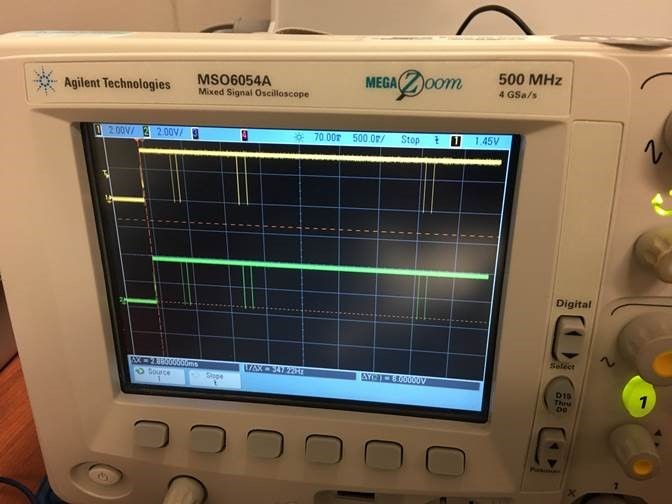
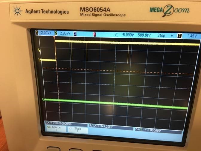
  • We got some wires soldered onto I2C1, SDA and SCK on the board with the bb timeout errors.

    There is activity on the SCK line, in that it jumps from 0V to 3.3V at board powerup, and I've captured the first 5 seconds on our scope.  *** However, the SDA line remains at 0V - likely indicating that either there's a problem or a wire soldering issue.

    We compared the SCK and SDA activity with a PCBA which boots Linux, and on that board there's activity on both SCK and SDA lines.

    Also, on the first board with just SCK doing something, the SCK pattern looks a little bit different than on the good board.  I will try to past my screenshots here:

    PCBA with Alleged Broken SDA I2C1 Lline:

    PCBA with good SDA I2C1 Line:

  • Jeff,

    This sounds very similar to what you reported here:

    You followed up that U4 was backward.  Could that have happened again?  I suspect a manufacturing issue somewhere.  I wouldn't expect the processor or PMIC to be forcing SDA low.

    By the way, your screenshots didn't come through.  You can't paste them.  You need to use the "Insert/Edit Media" icon:

    Brad

  •  Here is a trace of I2C1 line within the first ~5 seconds after power-up.

  • Here is the suspect board, also during the first 5 seconds after power-up.  

    I forgot to mention, yellow line (channel 1) is I2C1_CLK, green line (channel 2) is I2C1_SDA.  Channel 1 in both good and bad cases was the trigger channel.

  • Hey Brad,

    We had the technician remove 2 devices from I2C1 (U4 (temp sensor) and U8 (EEPROM)). The only device left should be the PMIC.

    With these 2 devices removed from the I2C1, the SPL is still reporting the same messages as in the previous post:

    2x (Timed out in wait_for_bb: status=1000)

    Trying to boot from MMC1

    Timed out in wait_for_bb: status=1000

    tps65903x: could not set LD01 voltage.
    2x (omap_hsmmc_send_cmd: timedout watiing on cmd inhibit to clear)
    spl: mmc init failed with error: -110
    SPL: failed to boot from all boot devices
    ### ERROR ### Please RESET the board ###
  • Can you measure the impedance to ground of SDA?  That might give us a clue as to whether there's an actual short in the board, or if somebody is misbehaving and driving the pin low.

    Is SDA still being held low after removing those other devices?  We need to find what's doing that.  You could poking around at some registers in the AM57xx via JTAG for starters, e.g. try changing the pinmux to see if that releases SDA.

  • With U4 and U8 removed from the board, had another hardware engineer double check the impedance (just used a DMM with the board powered off) around one of the resistors where SDA for I2C1 is pulled up (e.g. each end of the resistor pad to ground or pin 1 of the Linux console port), and both ends were OL or infinite impedance. Also measured the voltages on both pads of R16 and they were both 3.3V. Incidentally, this resistor, R16 was DNI on our board.

    Going to have the technician re-solder a wire to the pad of R16 which is connected to SDA i2c1 (or a better pad) to see if the SDA line assumes the correct voltages and post up.
  • What is R16? Are you saying there was no pullup on SDA of the failing board? Is the board working now?
  • Sorry for the long delay!!

    Re-checked both pads of R16 which pulls up the SDA and confirmed now that it was **NOT** populated on the board with the timeouts.

    Had the technician solder some leads so we could "clip on" a 2.2k resistor as required by the schematic.

    Following are the SPL console messages with and without the SDA pullup resistor, R16. Note that the timeout wait_for_bb and could not set LDO messages go away, which is great! Will grep the remaining strings in the SPL..

    Also, please note that there are 2 pullup resistors on I2C1 SDA and SCL the 5728EVM Rev A23 schematic. On our working boards, only R16 and R17 are populated, while R212 and R213 are unpopulated. Need to check what the 5728EVM/ BB-X15 do there, but my hardware engineers indicate that only 1 pullup should be needed, if that.

    ***************************************************************************
    SPL messages on Console Port with R16 (SDA pullup) unpopulated:
    ***************************************************************************
    U-Boot SPL 2017.01-g194b277-dirty (Apr 13 2018 - 14:05:16)
    DRA752-GP ES2.0
    Timed out in wait_for_bb: status=1000
    Timed out in wait_for_bb: status=1000
    Trying to boot from MMC1
    Timed out in wait_for_bb: status=1000
    tps65903x: could not set LDO1 voltage.
    omap_hsmmc_send_cmd: timedout waiting on cmd inhibit to clear
    omap_hsmmc_send_cmd: timedout waiting on cmd inhibit to clear
    spl: mmc init failed with error: -110
    SPL: failed to boot from all boot devices
    ### ERROR ### Please RESET the board ###

    ***************************************************************************
    SPL messages on Console Port with R16 (SDA pullup) POPULATED:
    ***************************************************************************
    U-Boot SPL 2017.01-g194b277-dirty (Apr 13 2018 - 14:05:16)
    DRA752-GP ES2.0
    Trying to boot from MMC1
    omap_hsmmc_send_cmd: timedout waiting on cmd inhibit to clear
    omap_hsmmc_send_cmd: timedout waiting on cmd inhibit to clear
    spl: mmc init failed with error: -110
    SPL: failed to boot from all boot devices
    ### ERROR ### Please RESET the board ###
  • It looks like adding the pullup fixed your issue with the I2C.  Those I2C-related messages are all gone now.  Though apparently that was not related to the MMC errors!

    You're booting from a card, right?  Can you post a similar comparison where you use the exact same card to boot one of the good boards and one of the bad boards?

  • We're currently booting from SD card. On our "good boards," we're able to flash the emmc and run from it. But right now, I've got a stand-alone SD card.

    Full disclosure, during the course of this thread, despite starting out with the TI SDK image, I switched back to the BeagleBone -based console image as that u-boot has the "correct" pinmux for our board. I also have the ti-processor-sdk-linux-am57xx-evm-04.01.00.06/ on my Linux machine, but for some reason, when I tried making an SD card using the scripts in SDK the bin directory, it only writes the MLO and not u-boot to the DOS partition.

    I just downloaded the latest TI SDK, and will generate a bootable SD card for it.

    In the meantime, following is the console output of a successful boot on one of our "good boards:"

    The previous post shows the bad board.

    Also, on a separate bad board, as noted above, it doesn't read from the SD card, but you can load the SPL via JTAG, and run it, and we don't see any error messages about I2C or MMC. it just won't boot, because I haven't yet figured out how to load u-boot to the relocation address. I followed the board porting instructions on the TI videos, but for some reason, that procedure didn't work for me. Mr. Rini suggested to look at the relocation code to figure out where and how to load u-boot via CCS/JTAG once the SPL completes..

    *************************************************************

    U-Boot SPL 2017.01-g194b277-dirty (Apr 13 2018 - 14:05:16)
    DRA752-GP ES2.0
    Trying to boot from MMC1

    ** Unable to use mmc 0:1 for loading the env **
    Using default environment

    board_fit_config_name() returns 0, match is am57xx-evm-reva3


    U-Boot 2017.01-g194b277-dirty (Apr 13 2018 - 14:05:16 -0500)

    CPU : DRA752-GP ES2.0
    Model: TI AM572x EVM Rev A3
    Board: Am572x Custom HW REV
    DRAM: 2 GiB
    MMC: OMAP SD/MMC: 0, OMAP SD/MMC: 1

    ** Unable to use mmc 0:1 for loading the env **
    Using default environment

    ti_i2c_eeprom_init failed 1
    setup_board_eeprom_env: am57xx_custom_hw_reva1
    SCSI: SATA link 0 timeout.
    AHCI 0001.0300 32 slots 1 ports 3 Gbps 0x1 impl SATA mode
    flags: 64bit ncq stag pm led clo only pmp pio slum part ccc apst
    scanning bus for devices...
    Found 0 device(s).
    Net: <ethaddr> not set. Validating first E-fuse MAC
    cpsw
    Press SPACE to abort autoboot in 2 seconds
    WARNING: Could not determine device tree to use
    usb_boot is currently disabled
    scsi_boot is currently disabled
    switch to partitions #0, OK
    mmc0 is current device
    Scanning mmc device 0
    Checking for: /uEnv.txt ...
    Checking for: /boot/uEnv.txt ...
    594 bytes read in 10 ms (57.6 KiB/s)
    Loaded environment from /boot/uEnv.txt
    Checking if uname_r is set in /boot/uEnv.txt ...
    debug: [uname_r=4.4.110-ti-r142] ...
    loading /boot/vmlinuz-4.4.110-ti-r142 ...
    8902320 bytes read in 394 ms (21.5 MiB/s)
    loading /boot/dtbs/4.4.110-ti-r142/am57xx-custom-hw-reva1.dtb ...
    151183 bytes read in 64 ms (2.3 MiB/s)
    loading /boot/initrd.img-4.4.110-ti-r142 ...
    5443956 bytes read in 248 ms (20.9 MiB/s)
    debug: [console=ttyO2,115200n8 root=/dev/mmcblk0p1 ro rootfstype=ext4 rootwait coheren.
    debug: [bootz 0x82000000 0x88080000:531174 0x88000000] ...
    ## Flattened Device Tree blob at 88000000
    Booting using the fdt blob at 0x88000000
    Loading Ramdisk to 8face000, end 8ffff174 ... OK
    Loading Device Tree to 8faa6000, end 8facde8e ... OK

    Starting kernel ...

    [ 0.065652] /cpus/cpu@0 missing clock-frequency property
    [ 0.065672] /cpus/cpu@1 missing clock-frequency property
    [ 1.274280] dra7-pcie 51000000.pcie_rc: link is not up
    [ 1.635491] omap_hsmmc 480b4000.mmc: no pinctrl state for sdr25 mode
    [ 1.642168] omap_hsmmc 480b4000.mmc: no pinctrl state for sdr12 mode
    [ 1.732844] omap_voltage_late_init: Voltage driver support not added
    Loading, please wait...
    [ 2.319186] hub 2-1:1.0: config failed, hub doesn't have any ports! (err -19)
    [ 2.831483] mmc2: error -22 whilst initialising SDIO card
    [ 3.232228] remoteproc0: failed to load am57xx-pru1_0-fw
    [ 3.238744] remoteproc0: request_firmware failed: -2
    [ 3.244071] pru-rproc 4b234000.pru0: rproc_boot failed
    [ 3.253615] remoteproc0: failed to load am57xx-pru1_1-fw
    [ 3.259632] remoteproc0: request_firmware failed: -2
    [ 3.264943] pru-rproc 4b238000.pru1: rproc_boot failed
    [ 3.294095] remoteproc0: failed to load am57xx-pru2_0-fw
    [ 3.303061] remoteproc0: request_firmware failed: -2
    [ 3.308398] pru-rproc 4b2b4000.pru0: rproc_boot failed
    [ 3.318683] remoteproc0: failed to load am57xx-pru2_1-fw
    [ 3.325499] remoteproc0: request_firmware failed: -2
    [ 3.330822] pru-rproc 4b2b8000.pru1: rproc_boot failed
    rootfs: recovering journal
    rootfs: clean, 43940/232320 files, 409282/967040 blocks
    [ 6.151809] remoteproc0: failed to load dra7-ipu1-fw.xem4
    [ 6.158436] remoteproc1: failed to load dra7-ipu2-fw.xem4
    [ 6.164281] remoteproc2: failed to load dra7-dsp1-fw.xe66
    [ 6.173795] remoteproc3: failed to load dra7-dsp2-fw.xe66
    [ 6.603221] tmp102 0-0048: error reading config register
    [ 6.899030] pixcir_ts 4-005c: pixcir_set_power_mode: can't read reg 0x33 : -121
    [ 6.906741] pixcir_ts 4-005c: Failed to set IDLE mode
    [ 7.074511] vpe 489d0000.vpe: couldn't get firmware
    [ OK ] Created slice system-systemd\x2dbacklight.slice.
    Starting Load/Save Screen Backlight...htness of backlight:backlight...
    [ OK ] Started Load/Save Screen Backlight Brightness of backlight:backlight.
    [ OK ] Reached target Sound Card.
    [ OK ] Started Raise network interfaces.
    [ OK ] Reached target Network.
    Starting Permit User Sessions...
    Starting OpenBSD Secure Shell server...
    Starting A high performance web server and a reverse proxy server...
    Starting /etc/rc.local Compatibility...
    [ OK ] Started Permit User Sessions.
    [ OK ] Started /etc/rc.local Compatibility.
    [ OK ] Started Getty on tty1.
    [ OK ] Started Serial Getty on ttyO2.
    [ OK ] Reached target Login Prompts.
    Starting BB WL18xx Bluetooth Service...
    [ OK ] Started BB WL18xx Bluetooth Service.
    [ OK ] Started OpenBSD Secure Shell server.
    [ OK ] Started A high performance web server and a reverse proxy server.
    [ OK ] Reached target Multi-User System.
    [ OK ] Reached target Graphical Interface.
    Starting Update UTMP about System Runlevel Changes...
    [ OK ] Started Update UTMP about System Runlevel Changes.

    ******************** ***********-X15 ttyO2

    .
    .
    .

    ***********-X15 login:

  • I was asking to use the same card in order to rule out any possible inconsistencies with the cards themselves.  Different cards may support different modes of operation.  For example, the issue might be related to support of UHS-I speeds, but perhaps you're not seeing the issue on the "good" board due to using a card that doesn't support UHS-I speeds.  So my request is to boot one of the good boards using a given card, then power down that board, transfer the card to a bad board, and see its corresponding behavior.

  • Yes sir,

    I'm sorry about confusing the issue by talking about multiple SD cards!!


    For the most recent tests, I used exactly the same SD card (SanDisk, 32GB micro SD HC I, 4 with a circle around it) with exactly the same Linux OS image on it on both the good PCBA and bad PCBA (where the surface mount R16 apparently fell off the board).

    The post from last-night and this morning were with that very same SD card, last-night booting from the bad PCBA - both without and with R16, the SDA pullup and this morning from the good PCBA from a different board house which boots into Linux.

    The bad board doesn't successfully make it out of the SPL, while the good board with the same SD card with the same image (SPL, u-boot, kernel, device tree, FS) boots all the way into Debian..

  • Thanks for clarifying. It sounds like we're aligned regarding the cards.

    I've been digging around to see what I could find regarding that specific issue, but I didn't see any silver bullets. So I think we should perhaps check some fundamentals... It would probably help if you could get a scope on the interface and take a look at the logic levels. What voltage is the signaling? Do the waveforms look clean? What frequency is it running at?
  • Yeah, well long story short - The latest batch of boards appear to have inconsistent missing (??or fallen off??) pullup resistors on the MMC1 lines for the SD card. Interestingly enough, our good boards have DNI for the resistors pulling up the MMC CLK signals for both MMC1 (SD) and MMC2 (emmc), whereas these are populated on the 572xEVM, Rev A3 board I have.

    Going to get with my team to see if it still makes sense to examine the quality of the MMC signals given the above..
  • The MMC/eMMC specifications don't require a pullup on CLK.  I'm not sure why so many TI boards put a pullup on CLK.  The other signals (RST#, CMD, DATx) require pullups.  I suggest that you start by populating the required pullups and re-test to see if that changes the behavior.