This thread has been locked.

If you have a related question, please click the "Ask a related question" button in the top right corner. The newly created question will be automatically linked to this question.

AM4377: ADC problem

Part Number: AM4377
Other Parts Discussed in Thread: LM60

Hi,

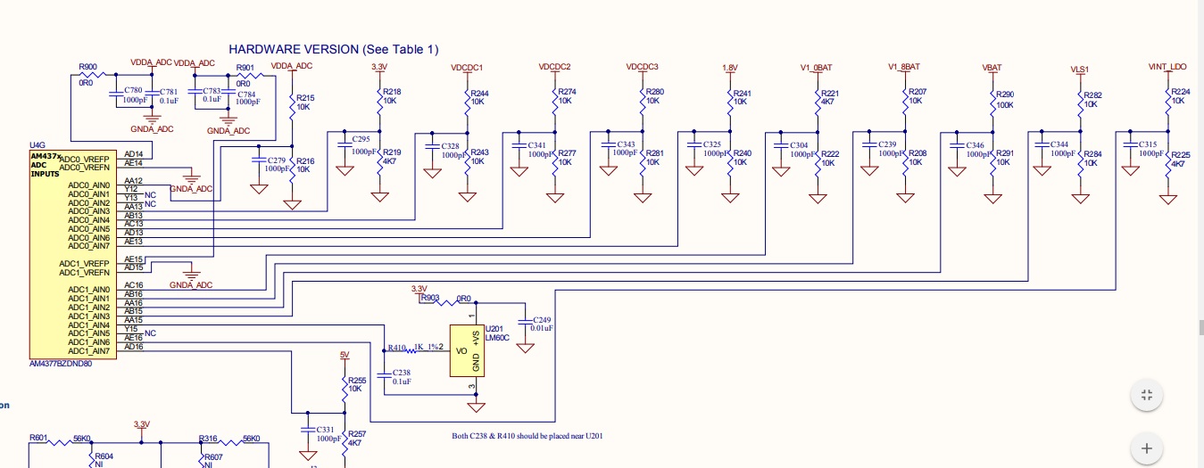
We are using AM4377 processor analog channels in one of our projects. While reading the value of a temperature sensor, we have observed some mismatch between the temperature used & read value. Then, we have isolated the sensor from processor(found temperature sensor output is proper) and found 1.8V always on the processor side. We could not see any information such as internal pull ups on ADC in datasheet or reference manual. What could be the reason for this 1.8V found on ADC channel ? and after disabling ADC also we could see 0.890V.We would like to know the reason for that also.
Complete part no of the processor used: AM4377BZDND80

Appreciate your quick response.

  • Hi,

    What software are you using? Which version? How is the ADC configured?
  • Hi Biser,

    we are  using  ti-linux-sdk-4.00.00.04, Linux Kernel 4.9.28+ (2017 LTS). we have backported ADC1 driver made for v3.2.0.5, Here is the patch we have applied. We are getting a proper reading on other channels.

    From 5dba9558a46a19c06af4db97a18bc7430069d761 Mon Sep 17 00:00:00 2001
    From: Umesh Krishnan <umeshk@mistralsolutions.com>
    Date: Wed, 25 Oct 2017 16:43:38 +0530
    Subject: [PATCH 1/7] VBAT voltage reading using ADC1 enabled.
    
    ADC1 channel 2 is used for reading vbat voltage.
    
    Signed-off-by: Umesh Krishnan <umeshk@mistralsolutions.com>
    ---
     arch/arm/boot/dts/am4372.dtsi               |  26 ++-
     arch/arm/boot/dts/am437x-sk-evm.dts         |  12 ++
     arch/arm/boot/dts/am43xx-clocks.dtsi        |   8 +
     arch/arm/configs/gc150_am437x-evm_defconfig |   6 +-
     arch/arm/mach-omap2/omap_hwmod_43xx_data.c  |  38 ++++
     arch/arm/mach-omap2/prcm43xx.h              |   1 +
     drivers/clk/ti/clk-43xx.c                   |   1 +
     drivers/iio/adc/ti_am335x_adc.c             | 128 +++++--------
     drivers/input/misc/Kconfig                  |   6 +
     drivers/input/misc/Makefile                 |   1 +
     drivers/input/touchscreen/ti_am335x_tsc.c   | 152 +++++++---------
     drivers/mfd/ti_am335x_tscadc.c              | 270 ++++++++++++++++++++--------
     include/linux/mfd/ti_am335x_tscadc.h        |  91 +++++++++-
     include/uapi/linux/Kbuild                   |   1 +
     14 files changed, 481 insertions(+), 260 deletions(-)
    
    diff --git a/arch/arm/boot/dts/am4372.dtsi b/arch/arm/boot/dts/am4372.dtsi
    index 8dde149..437d8e4 100644
    --- a/arch/arm/boot/dts/am4372.dtsi
    +++ b/arch/arm/boot/dts/am4372.dtsi
    @@ -901,7 +901,7 @@
     		};
     
     		tscadc: tscadc@44e0d000 {
    -			compatible = "ti,am3359-tscadc";
    +			compatible = "ti,am4372-tscadc","ti,am3359-tscadc";
     			reg = <0x44e0d000 0x1000>;
     			ti,hwmods = "adc_tsc";
     			interrupts = <GIC_SPI 16 IRQ_TYPE_LEVEL_HIGH>;
    @@ -912,16 +912,36 @@
     			dma-names = "fifo0", "fifo1";
     
     			tsc {
    -				compatible = "ti,am3359-tsc";
    +				compatible = "ti,am4372-tsc","ti,am3359-tsc";
     			};
     
     			adc {
     				#io-channel-cells = <1>;
    -				compatible = "ti,am3359-adc";
    +				compatible = "ti,am4372-adc","ti,am3359-adc";
     			};
     
     		};
     
    +		magadc: magadc@4834c000 {
    +			compatible = "ti,am4372-magadc";
    +			reg = <0x4834c000 0x2000>;
    +			ti,hwmods = "adc_mag";
    +			dmas = <&edma 54>;
    +			dma-names = "rx";
    +			interrupts = <GIC_SPI 115 IRQ_TYPE_LEVEL_HIGH>;
    +			clocks = <&adc_mag_fck>;
    +			clock-names = "fck";
    +			status = "disabled";
    +
    +			mag {
    +				compatible = "ti,am4372-mag";
    +			};
    +
    +			adc {
    +				compatible ="ti,am4372-adc";
    +			};
    +		};
    +
     		sham: sham@53100000 {
     			compatible = "ti,omap5-sham";
     			ti,hwmods = "sham";
    diff --git a/arch/arm/boot/dts/am437x-sk-evm.dts b/arch/arm/boot/dts/am437x-sk-evm.dts
    index 66422b2..f24c5ab 100644
    --- a/arch/arm/boot/dts/am437x-sk-evm.dts
    +++ b/arch/arm/boot/dts/am437x-sk-evm.dts
    @@ -688,6 +688,18 @@
     	pinctrl-0 = <&ecap0_pins>;
     };
     
    +&magadc {
    +	status = "okay";
    +
    +	mag {
    +			ti,tracks = <0>;
    +	};
    +
    +	adc {
    +			ti,adc-channels = <2>;
    +	};
    +};
    +
     &gpio0 {
     	status = "okay";
     };
    diff --git a/arch/arm/boot/dts/am43xx-clocks.dtsi b/arch/arm/boot/dts/am43xx-clocks.dtsi
    index d1d73b7..0ba2522 100644
    --- a/arch/arm/boot/dts/am43xx-clocks.dtsi
    +++ b/arch/arm/boot/dts/am43xx-clocks.dtsi
    @@ -40,6 +40,14 @@
     		clock-div = <1>;
     	};
     
    +	adc_mag_fck: adc_mag_fck {
    +		#clock-cells = <0>;
    +		compatible = "fixed-factor-clock";
    +		clocks = <&sys_clkin_ck>;
    +		clock-mult = <1>;
    +		clock-div = <1>;
    +	};
    +
     	dcan0_fck: dcan0_fck {
     		#clock-cells = <0>;
     		compatible = "fixed-factor-clock";
    diff --git a/arch/arm/configs/gc150_am437x-evm_defconfig b/arch/arm/configs/gc150_am437x-evm_defconfig
    index 45f89e9..fd70dd5 100644
    --- a/arch/arm/configs/gc150_am437x-evm_defconfig
    +++ b/arch/arm/configs/gc150_am437x-evm_defconfig
    @@ -347,7 +347,7 @@ CONFIG_TOUCHSCREEN_ATMEL_MXT=m
     CONFIG_TOUCHSCREEN_GOODIX=m
     CONFIG_TOUCHSCREEN_MMS114=m
     CONFIG_TOUCHSCREEN_EDT_FT5X06=m
    -CONFIG_TOUCHSCREEN_TI_AM335X_TSC=m
    +CONFIG_TOUCHSCREEN_TI_AM335X_TSC=y
     CONFIG_TOUCHSCREEN_PIXCIR=m
     CONFIG_TOUCHSCREEN_ST1232=m
     CONFIG_INPUT_MISC=y
    @@ -433,7 +433,7 @@ CONFIG_OMAP_WATCHDOG=m
     CONFIG_BCMA=y
     CONFIG_MFD_ACT8945A=y
     CONFIG_MFD_AXP20X_I2C=m
    -CONFIG_MFD_TI_AM335X_TSCADC=m
    +CONFIG_MFD_TI_AM335X_TSCADC=y
     CONFIG_MFD_PALMAS=y
     CONFIG_MFD_TPS65090=y
     CONFIG_MFD_TPS65217=y
    @@ -640,7 +640,7 @@ CONFIG_EXTCON_PALMAS=m
     CONFIG_EXTCON_USB_GPIO=m
     CONFIG_TI_EMIF_SRAM=m
     CONFIG_IIO=y
    -CONFIG_TI_AM335X_ADC=m
    +CONFIG_TI_AM335X_ADC=y
     CONFIG_VF610_ADC=m
     CONFIG_CM36651=m
     CONFIG_AK8975=y
    diff --git a/arch/arm/mach-omap2/omap_hwmod_43xx_data.c b/arch/arm/mach-omap2/omap_hwmod_43xx_data.c
    index afbce1f..f866aff 100644
    --- a/arch/arm/mach-omap2/omap_hwmod_43xx_data.c
    +++ b/arch/arm/mach-omap2/omap_hwmod_43xx_data.c
    @@ -442,6 +442,36 @@
     	},
     };
     
    +/*
    + * 'adc/mag' class
    + * MagCard Controller (Anolog-To-Digital Converter)
    + */
    +static struct omap_hwmod_class_sysconfig am43xx_adc_mag_sysc = {
    +	.rev_offs	= 0x00,
    +	.sysc_offs	= 0x10,
    +	.sysc_flags	= SYSC_HAS_SIDLEMODE,
    +	.idlemodes	= (SIDLE_FORCE | SIDLE_NO | SIDLE_SMART),
    +	.sysc_fields	= &omap_hwmod_sysc_type2,
    +};
    +
    +static struct omap_hwmod_class am43xx_adc_mag_hwmod_class = {
    +	.name		= "adc_mag",
    +	.sysc		= &am43xx_adc_mag_sysc,
    +};
    +
    +static struct omap_hwmod am43xx_adc_mag_hwmod = {
    +	.name		= "adc_mag",
    +	.class		= &am43xx_adc_mag_hwmod_class,
    +	.clkdm_name	= "l3s_clkdm",
    +	.main_clk	= "adc_mag_fck",
    +	.prcm		= {
    +		.omap4  = {
    +			.clkctrl_offs	= AM43XX_CM_PER_MAGADC_CLKCTRL_OFFSET,
    +			.modulemode	= MODULEMODE_SWCTRL,
    +		},
    +	},
    +};
    +
     static struct omap_hwmod_class_sysconfig am43xx_des_sysc = {
     	.rev_offs	= 0x30,
     	.sysc_offs	= 0x34,
    @@ -678,6 +708,13 @@
     	.user           = OCP_USER_MPU,
     };
     
    +static struct omap_hwmod_ocp_if am43xx_l4_ls__adc_mag = {
    +	.master		= &am33xx_l4_ls_hwmod,
    +	.slave		= &am43xx_adc_mag_hwmod,
    +	.clk		= "dpll_core_m4_div2_ck",
    +	.user		= OCP_USER_MPU,
    +};
    +
     static struct omap_hwmod_ocp_if am43xx_l4_hs__cpgmac0 = {
     	.master		= &am43xx_l4_hs_hwmod,
     	.slave		= &am33xx_cpgmac0_hwmod,
    @@ -997,6 +1034,7 @@
     	&am43xx_l3__vpfe1,
     	&am43xx_l4_ls__vpfe0,
     	&am43xx_l4_ls__vpfe1,
    +	&am43xx_l4_ls__adc_mag,
     	NULL,
     };
     
    diff --git a/arch/arm/mach-omap2/prcm43xx.h b/arch/arm/mach-omap2/prcm43xx.h
    index 7078a61..1dccf62 100644
    --- a/arch/arm/mach-omap2/prcm43xx.h
    +++ b/arch/arm/mach-omap2/prcm43xx.h
    @@ -118,6 +118,7 @@
     #define AM43XX_CM_PER_MMC2_CLKCTRL_OFFSET		0x0248
     #define AM43XX_CM_PER_QSPI_CLKCTRL_OFFSET               0x0258
     #define AM43XX_CM_PER_GPMC_CLKCTRL_OFFSET		0x0220
    +#define AM43XX_CM_PER_MAGADC_CLKCTRL_OFFSET		0x0230
     #define AM43XX_CM_PER_MCASP0_CLKCTRL_OFFSET		0x0238
     #define AM43XX_CM_PER_MCASP1_CLKCTRL_OFFSET		0x0240
     #define AM43XX_CM_PER_L4LS_CLKCTRL_OFFSET		0x0420
    diff --git a/drivers/clk/ti/clk-43xx.c b/drivers/clk/ti/clk-43xx.c
    index e816a75..a82bc8c 100644
    --- a/drivers/clk/ti/clk-43xx.c
    +++ b/drivers/clk/ti/clk-43xx.c
    @@ -47,6 +47,7 @@
     	DT_CLK(NULL, "dpll_per_m2_div4_wkupdm_ck", "dpll_per_m2_div4_wkupdm_ck"),
     	DT_CLK(NULL, "dpll_per_m2_div4_ck", "dpll_per_m2_div4_ck"),
     	DT_CLK(NULL, "adc_tsc_fck", "adc_tsc_fck"),
    +	DT_CLK(NULL, "adc_mag_fck", "adc_mag_fck"),
     	DT_CLK(NULL, "clkdiv32k_ck", "clkdiv32k_ck"),
     	DT_CLK(NULL, "clkdiv32k_ick", "clkdiv32k_ick"),
     	DT_CLK(NULL, "dcan0_fck", "dcan0_fck"),
    diff --git a/drivers/iio/adc/ti_am335x_adc.c b/drivers/iio/adc/ti_am335x_adc.c
    index 4282cec..7c85612 100644
    --- a/drivers/iio/adc/ti_am335x_adc.c
    +++ b/drivers/iio/adc/ti_am335x_adc.c
    @@ -13,6 +13,7 @@
      * GNU General Public License for more details.
      */
     
    +#include <linux/init.h>
     #include <linux/kernel.h>
     #include <linux/err.h>
     #include <linux/module.h>
    @@ -49,14 +50,12 @@ struct tiadc_dma {
     struct tiadc_device {
     	struct ti_tscadc_dev *mfd_tscadc;
     	struct tiadc_dma dma;
    -	struct mutex fifo1_lock; /* to protect fifo access */
     	int channels;
     	int total_ch_enabled;
     	u8 channel_line[8];
     	u8 channel_step[8];
     	int buffer_en_ch_steps;
     	u16 data[8];
    -	u32 open_delay[8], sample_delay[8], step_avg[8];
     };
     
     static unsigned int tiadc_readl(struct tiadc_device *adc, unsigned int reg)
    @@ -105,61 +104,34 @@ static u32 get_adc_step_bit(struct tiadc_device *adc_dev, int chan)
     static void tiadc_step_config(struct iio_dev *indio_dev)
     {
     	struct tiadc_device *adc_dev = iio_priv(indio_dev);
    -	struct device *dev = adc_dev->mfd_tscadc->dev;
     	unsigned int stepconfig;
    -	int i, steps = 0;
    +	int i, steps;
     
     	/*
     	 * There are 16 configurable steps and 8 analog input
     	 * lines available which are shared between Touchscreen and ADC.
     	 *
    -	 * Steps forwards i.e. from 0 towards 16 are used by ADC
    +	 * Steps backwards i.e. from 16 towards 0 are used by ADC
     	 * depending on number of input lines needed.
     	 * Channel would represent which analog input
     	 * needs to be given to ADC to digitalize data.
     	 */
     
    +	steps = 0;
    +	if (iio_buffer_enabled(indio_dev))
    +		stepconfig = STEPCONFIG_AVG_16 | STEPCONFIG_FIFO1
    +					| STEPCONFIG_MODE_SWCNT;
    +	else
    +		stepconfig = STEPCONFIG_AVG_16 | STEPCONFIG_FIFO1;
     
     	for (i = 0; i < adc_dev->channels; i++) {
     		int chan;
     
     		chan = adc_dev->channel_line[i];
    -
    -		if (adc_dev->step_avg[i] > STEPCONFIG_AVG_16) {
    -			dev_warn(dev, "chan %d step_avg truncating to %d\n",
    -				 chan, STEPCONFIG_AVG_16);
    -			adc_dev->step_avg[i] = STEPCONFIG_AVG_16;
    -		}
    -
    -		if (adc_dev->step_avg[i])
    -			stepconfig =
    -			STEPCONFIG_AVG(ffs(adc_dev->step_avg[i]) - 1) |
    -			STEPCONFIG_FIFO1;
    -		else
    -			stepconfig = STEPCONFIG_FIFO1;
    -
    -		if (iio_buffer_enabled(indio_dev))
    -			stepconfig |= STEPCONFIG_MODE_SWCNT;
    -
     		tiadc_writel(adc_dev, REG_STEPCONFIG(steps),
     				stepconfig | STEPCONFIG_INP(chan));
    -
    -		if (adc_dev->open_delay[i] > STEPDELAY_OPEN_MASK) {
    -			dev_warn(dev, "chan %d open delay truncating to 0x3FFFF\n",
    -				 chan);
    -			adc_dev->open_delay[i] = STEPDELAY_OPEN_MASK;
    -		}
    -
    -		if (adc_dev->sample_delay[i] > 0xFF) {
    -			dev_warn(dev, "chan %d sample delay truncating to 0xFF\n",
    -				 chan);
    -			adc_dev->sample_delay[i] = 0xFF;
    -		}
    -
     		tiadc_writel(adc_dev, REG_STEPDELAY(steps),
    -				STEPDELAY_OPEN(adc_dev->open_delay[i]) |
    -				STEPDELAY_SAMPLE(adc_dev->sample_delay[i]));
    -
    +				STEPCONFIG_OPENDLY);
     		adc_dev->channel_step[i] = steps;
     		steps++;
     	}
    @@ -308,13 +280,14 @@ static int tiadc_buffer_preenable(struct iio_dev *indio_dev)
     static int tiadc_buffer_postenable(struct iio_dev *indio_dev)
     {
     	struct tiadc_device *adc_dev = iio_priv(indio_dev);
    +	struct iio_buffer *buffer = indio_dev->buffer;
     	struct tiadc_dma *dma = &adc_dev->dma;
     	unsigned int irq_enable;
     	unsigned int enb = 0;
     	u8 bit;
     
     	tiadc_step_config(indio_dev);
    -	for_each_set_bit(bit, indio_dev->active_scan_mask, adc_dev->channels) {
    +	for_each_set_bit(bit, buffer->scan_mask, adc_dev->channels) {
     		enb |= (get_adc_step_bit(adc_dev, bit) << 1);
     		adc_dev->total_ch_enabled++;
     	}
    @@ -396,10 +369,15 @@ static int tiadc_iio_buffered_hardware_setup(struct iio_dev *indio_dev,
     		goto error_kfifo_free;
     
     	indio_dev->setup_ops = setup_ops;
    -	indio_dev->modes |= INDIO_BUFFER_SOFTWARE;
    +	indio_dev->modes |= INDIO_BUFFER_HARDWARE;
    +
    +	if (ret)
    +		goto error_free_irq;
     
     	return 0;
     
    +error_free_irq:
    +	free_irq(irq, indio_dev);
     error_kfifo_free:
     	iio_kfifo_free(indio_dev->buffer);
     	return ret;
    @@ -466,7 +444,6 @@ static int tiadc_read_raw(struct iio_dev *indio_dev,
     		int *val, int *val2, long mask)
     {
     	struct tiadc_device *adc_dev = iio_priv(indio_dev);
    -	int ret = IIO_VAL_INT;
     	int i, map_val;
     	unsigned int fifo1count, read, stepid;
     	bool found = false;
    @@ -480,14 +457,13 @@ static int tiadc_read_raw(struct iio_dev *indio_dev,
     	if (!step_en)
     		return -EINVAL;
     
    -	mutex_lock(&adc_dev->fifo1_lock);
     	fifo1count = tiadc_readl(adc_dev, REG_FIFO1CNT);
     	while (fifo1count--)
     		tiadc_readl(adc_dev, REG_FIFO1);
     
     	am335x_tsc_se_set_once(adc_dev->mfd_tscadc, step_en);
     
    -	timeout = jiffies + msecs_to_jiffies
    +	timeout = jiffies + usecs_to_jiffies
     				(IDLE_TIMEOUT * adc_dev->channels);
     	/* Wait for Fifo threshold interrupt */
     	while (1) {
    @@ -497,8 +473,7 @@ static int tiadc_read_raw(struct iio_dev *indio_dev,
     
     		if (time_after(jiffies, timeout)) {
     			am335x_tsc_se_adc_done(adc_dev->mfd_tscadc);
    -			ret = -EAGAIN;
    -			goto err_unlock;
    +			return -EAGAIN;
     		}
     	}
     	map_val = adc_dev->channel_step[chan->scan_index];
    @@ -524,11 +499,8 @@ static int tiadc_read_raw(struct iio_dev *indio_dev,
     	am335x_tsc_se_adc_done(adc_dev->mfd_tscadc);
     
     	if (found == false)
    -		ret =  -EBUSY;
    -
    -err_unlock:
    -	mutex_unlock(&adc_dev->fifo1_lock);
    -	return ret;
    +		return -EBUSY;
    +	return IIO_VAL_INT;
     }
     
     static const struct iio_info tiadc_info = {
    @@ -571,43 +543,17 @@ static int tiadc_request_dma(struct platform_device *pdev,
     	return -ENOMEM;
     }
     
    -static int tiadc_parse_dt(struct platform_device *pdev,
    -			  struct tiadc_device *adc_dev)
    -{
    -	struct device_node *node = pdev->dev.of_node;
    -	struct property *prop;
    -	const __be32 *cur;
    -	int channels = 0;
    -	u32 val;
    -
    -	of_property_for_each_u32(node, "ti,adc-channels", prop, cur, val) {
    -		adc_dev->channel_line[channels] = val;
    -
    -		/* Set Default values for optional DT parameters */
    -		adc_dev->open_delay[channels] = STEPCONFIG_OPENDLY;
    -		adc_dev->sample_delay[channels] = STEPCONFIG_SAMPLEDLY;
    -		adc_dev->step_avg[channels] = 16;
    -
    -		channels++;
    -	}
    -
    -	of_property_read_u32_array(node, "ti,chan-step-avg",
    -				   adc_dev->step_avg, channels);
    -	of_property_read_u32_array(node, "ti,chan-step-opendelay",
    -				   adc_dev->open_delay, channels);
    -	of_property_read_u32_array(node, "ti,chan-step-sampledelay",
    -				   adc_dev->sample_delay, channels);
    -
    -	adc_dev->channels = channels;
    -	return 0;
    -}
    -
     static int tiadc_probe(struct platform_device *pdev)
     {
     	struct iio_dev		*indio_dev;
     	struct tiadc_device	*adc_dev;
     	struct device_node	*node = pdev->dev.of_node;
    +	struct property		*prop;
    +	const __be32		*cur;
     	int			err;
    +	u32			val;
    +	int			channels = 0;
    +	int irq;
     
     	if (!node) {
     		dev_err(&pdev->dev, "Could not find valid DT data.\n");
    @@ -622,7 +568,12 @@ static int tiadc_probe(struct platform_device *pdev)
     	adc_dev = iio_priv(indio_dev);
     
     	adc_dev->mfd_tscadc = ti_tscadc_dev_get(pdev);
    -	tiadc_parse_dt(pdev, adc_dev);
    +
    +	of_property_for_each_u32(node, "ti,adc-channels", prop, cur, val) {
    +		adc_dev->channel_line[channels] = val;
    +		channels++;
    +	}
    +	adc_dev->channels = channels;
     
     	indio_dev->dev.parent = &pdev->dev;
     	indio_dev->name = dev_name(&pdev->dev);
    @@ -631,16 +582,19 @@ static int tiadc_probe(struct platform_device *pdev)
     
     	tiadc_step_config(indio_dev);
     	tiadc_writel(adc_dev, REG_FIFO1THR, FIFO1_THRESHOLD);
    -	mutex_init(&adc_dev->fifo1_lock);
    -
     	err = tiadc_channel_init(indio_dev, adc_dev->channels);
     	if (err < 0)
     		return err;
    -
    +	/* FIXME
    +	if (adc_dev->mfd_tscadc->use_mag)
    +		irq = adc_dev->mfd_tscadc->magirq;
    +	else
    +		irq = adc_dev->mfd_tscadc->irq;
    +	*/
     	err = tiadc_iio_buffered_hardware_setup(indio_dev,
     		&tiadc_worker_h,
     		&tiadc_irq_h,
    -		adc_dev->mfd_tscadc->irq,
    +		adc_dev->mfd_tscadc->magirq,
     		IRQF_SHARED,
     		&tiadc_buffer_setup_ops);
     
    @@ -729,6 +683,7 @@ static int __maybe_unused tiadc_resume(struct device *dev)
     
     static const struct of_device_id ti_adc_dt_ids[] = {
     	{ .compatible = "ti,am3359-adc", },
    +	{ .compatible = "ti,am4372-adc", },
     	{ }
     };
     MODULE_DEVICE_TABLE(of, ti_adc_dt_ids);
    @@ -736,6 +691,7 @@ static int __maybe_unused tiadc_resume(struct device *dev)
     static struct platform_driver tiadc_driver = {
     	.driver = {
     		.name   = "TI-am335x-adc",
    +		.owner  = THIS_MODULE,
     		.pm	= &tiadc_pm_ops,
     		.of_match_table = ti_adc_dt_ids,
     	},
    diff --git a/drivers/input/misc/Kconfig b/drivers/input/misc/Kconfig
    index 7ffb614..feb79d0 100644
    --- a/drivers/input/misc/Kconfig
    +++ b/drivers/input/misc/Kconfig
    @@ -831,4 +831,10 @@ config INPUT_HISI_POWERKEY
     	  To compile this driver as a module, choose M here: the
     	  module will be called hisi_powerkey.
     
    +config INPUT_MAG_ADC
    +	tristate "Magnetic Card Reader Driver for AM43xx"
    +	depends on SOC_AM43XX
    +	help
    +	Say Y here if you want to enable MSR driver for AM43XX
    +
     endif
    diff --git a/drivers/input/misc/Makefile b/drivers/input/misc/Makefile
    index 0b6d025..1d85310 100644
    --- a/drivers/input/misc/Makefile
    +++ b/drivers/input/misc/Makefile
    @@ -78,3 +78,4 @@ obj-$(CONFIG_INPUT_WM831X_ON)		+= wm831x-on.o
     obj-$(CONFIG_INPUT_XEN_KBDDEV_FRONTEND)	+= xen-kbdfront.o
     obj-$(CONFIG_INPUT_YEALINK)		+= yealink.o
     obj-$(CONFIG_INPUT_IDEAPAD_SLIDEBAR)	+= ideapad_slidebar.o
    +obj-$(CONFIG_INPUT_MAG_ADC)		+= ti_magadc.o
    diff --git a/drivers/input/touchscreen/ti_am335x_tsc.c b/drivers/input/touchscreen/ti_am335x_tsc.c
    index d1ae8c2..f317a67 100644
    --- a/drivers/input/touchscreen/ti_am335x_tsc.c
    +++ b/drivers/input/touchscreen/ti_am335x_tsc.c
    @@ -26,8 +26,6 @@
     #include <linux/delay.h>
     #include <linux/of.h>
     #include <linux/of_device.h>
    -#include <linux/sort.h>
    -#include <linux/pm_wakeirq.h>
     
     #include <linux/mfd/ti_am335x_tscadc.h>
     
    @@ -55,6 +53,8 @@ struct titsc {
     	u32			inp_xp, inp_xn, inp_yp, inp_yn;
     	u32			step_mask;
     	u32			charge_delay;
    +	u32			prev_x, prev_y, prev_z;
    +	bool			event_pending;
     };
     
     static unsigned int titsc_readl(struct titsc *ts, unsigned int reg)
    @@ -206,68 +206,63 @@ static void titsc_step_config(struct titsc *ts_dev)
     	am335x_tsc_se_set_cache(ts_dev->mfd_tscadc, ts_dev->step_mask);
     }
     
    -static int titsc_cmp_coord(const void *a, const void *b)
    -{
    -	return *(int *)a - *(int *)b;
    -}
    -
     static void titsc_read_coordinates(struct titsc *ts_dev,
     		u32 *x, u32 *y, u32 *z1, u32 *z2)
     {
    -	unsigned int yvals[7], xvals[7];
    -	unsigned int i, xsum = 0, ysum = 0;
    +	unsigned int fifocount = titsc_readl(ts_dev, REG_FIFO0CNT);
    +	unsigned int prev_val_x = ~0, prev_val_y = ~0;
    +	unsigned int prev_diff_x = ~0, prev_diff_y = ~0;
    +	unsigned int read, diff;
    +	unsigned int i, channel;
     	unsigned int creads = ts_dev->coordinate_readouts;
    +	unsigned int first_step = TOTAL_STEPS - (creads * 2 + 2);
     
    -	for (i = 0; i < creads; i++) {
    -		yvals[i] = titsc_readl(ts_dev, REG_FIFO0);
    -		yvals[i] &= 0xfff;
    -	}
    +	*z1 = *z2 = 0;
    +	if (fifocount % (creads * 2 + 2))
    +		fifocount -= fifocount % (creads * 2 + 2);
    +	/*
    +	 * Delta filter is used to remove large variations in sampled
    +	 * values from ADC. The filter tries to predict where the next
    +	 * coordinate could be. This is done by taking a previous
    +	 * coordinate and subtracting it form current one. Further the
    +	 * algorithm compares the difference with that of a present value,
    +	 * if true the value is reported to the sub system.
    +	 */
    +	for (i = 0; i < fifocount; i++) {
    +		read = titsc_readl(ts_dev, REG_FIFO0);
    +
    +		channel = (read & 0xf0000) >> 16;
    +		read &= 0xfff;
    +		if (channel > first_step + creads + 2) {
    +			diff = abs(read - prev_val_x);
    +			if (diff < prev_diff_x) {
    +				prev_diff_x = diff;
    +				*x = read;
    +			}
    +			prev_val_x = read;
     
    -	*z1 = titsc_readl(ts_dev, REG_FIFO0);
    -	*z1 &= 0xfff;
    -	*z2 = titsc_readl(ts_dev, REG_FIFO0);
    -	*z2 &= 0xfff;
    +		} else if (channel == first_step + creads + 1) {
    +			*z1 = read;
     
    -	for (i = 0; i < creads; i++) {
    -		xvals[i] = titsc_readl(ts_dev, REG_FIFO0);
    -		xvals[i] &= 0xfff;
    -	}
    +		} else if (channel == first_step + creads + 2) {
    +			*z2 = read;
     
    -	/*
    -	 * If co-ordinates readouts is less than 4 then
    -	 * report the average. In case of 4 or more
    -	 * readouts, sort the co-ordinate samples, drop
    -	 * min and max values and report the average of
    -	 * remaining values.
    -	 */
    -	if (creads <=  3) {
    -		for (i = 0; i < creads; i++) {
    -			ysum += yvals[i];
    -			xsum += xvals[i];
    -		}
    -		ysum /= creads;
    -		xsum /= creads;
    -	} else {
    -		sort(yvals, creads, sizeof(unsigned int),
    -		     titsc_cmp_coord, NULL);
    -		sort(xvals, creads, sizeof(unsigned int),
    -		     titsc_cmp_coord, NULL);
    -		for (i = 1; i < creads - 1; i++) {
    -			ysum += yvals[i];
    -			xsum += xvals[i];
    +		} else if (channel > first_step) {
    +			diff = abs(read - prev_val_y);
    +			if (diff < prev_diff_y) {
    +				prev_diff_y = diff;
    +				*y = read;
    +			}
    +			prev_val_y = read;
     		}
    -		ysum /= creads - 2;
    -		xsum /= creads - 2;
     	}
    -	*y = ysum;
    -	*x = xsum;
     }
     
     static irqreturn_t titsc_irq(int irq, void *dev)
     {
     	struct titsc *ts_dev = dev;
     	struct input_dev *input_dev = ts_dev->input;
    -	unsigned int fsm, status, irqclr = 0;
    +	unsigned int status, irqclr = 0;
     	unsigned int x = 0, y = 0;
     	unsigned int z1, z2, z;
     
    @@ -275,21 +270,22 @@ static irqreturn_t titsc_irq(int irq, void *dev)
     	if (status & IRQENB_HW_PEN) {
     		ts_dev->pen_down = true;
     		irqclr |= IRQENB_HW_PEN;
    -		pm_stay_awake(ts_dev->mfd_tscadc->dev);
     	}
     
     	if (status & IRQENB_PENUP) {
    -		fsm = titsc_readl(ts_dev, REG_ADCFSM);
    -		if (fsm == ADCFSM_STEPID) {
    -			ts_dev->pen_down = false;
    -			input_report_key(input_dev, BTN_TOUCH, 0);
    -			input_report_abs(input_dev, ABS_PRESSURE, 0);
    -			input_sync(input_dev);
    -			pm_relax(ts_dev->mfd_tscadc->dev);
    -		} else {
    -			ts_dev->pen_down = true;
    -		}
    +		ts_dev->pen_down = false;
    +		input_report_key(input_dev, BTN_TOUCH, 0);
    +		input_report_abs(input_dev, ABS_PRESSURE, 0);
    +		input_sync(input_dev);
     		irqclr |= IRQENB_PENUP;
    +		ts_dev->event_pending = false;
    +	} else if (ts_dev->event_pending == true) {
    +		input_report_abs(input_dev, ABS_X, ts_dev->prev_x);
    +		input_report_abs(input_dev, ABS_Y, ts_dev->prev_y);
    +		input_report_abs(input_dev, ABS_PRESSURE, ts_dev->prev_z);
    +		input_report_key(input_dev, BTN_TOUCH, 1);
    +		input_sync(input_dev);
    +		ts_dev->event_pending = false;
     	}
     
     	if (status & IRQENB_EOS)
    @@ -316,20 +312,17 @@ static irqreturn_t titsc_irq(int irq, void *dev)
     			z = (z + 2047) >> 12;
     
     			if (z <= MAX_12BIT) {
    -				input_report_abs(input_dev, ABS_X, x);
    -				input_report_abs(input_dev, ABS_Y, y);
    -				input_report_abs(input_dev, ABS_PRESSURE, z);
    -				input_report_key(input_dev, BTN_TOUCH, 1);
    -				input_sync(input_dev);
    +				ts_dev->prev_x = x;
    +				ts_dev->prev_y = y;
    +				ts_dev->prev_z = z;
    +				ts_dev->event_pending = true;
     			}
     		}
     		irqclr |= IRQENB_FIFO0THRES;
     	}
     	if (irqclr) {
     		titsc_writel(ts_dev, REG_IRQSTATUS, irqclr);
    -		if (status & IRQENB_EOS)
    -			am335x_tsc_se_set_cache(ts_dev->mfd_tscadc,
    -						ts_dev->step_mask);
    +		am335x_tsc_se_set_cache(ts_dev->mfd_tscadc, ts_dev->step_mask);
     		return IRQ_HANDLED;
     	}
     	return IRQ_NONE;
    @@ -367,21 +360,12 @@ static int titsc_parse_dt(struct platform_device *pdev,
     	 */
     	err = of_property_read_u32(node, "ti,coordinate-readouts",
     			&ts_dev->coordinate_readouts);
    -	if (err < 0) {
    -		dev_warn(&pdev->dev, "please use 'ti,coordinate-readouts' instead\n");
    +	if (err < 0)
     		err = of_property_read_u32(node, "ti,coordiante-readouts",
     				&ts_dev->coordinate_readouts);
    -	}
    -
     	if (err < 0)
     		return err;
     
    -	if (ts_dev->coordinate_readouts <= 0) {
    -		dev_warn(&pdev->dev,
    -			 "invalid co-ordinate readouts, resetting it to 5\n");
    -		ts_dev->coordinate_readouts = 5;
    -	}
    -
     	err = of_property_read_u32(node, "ti,charge-delay",
     				   &ts_dev->charge_delay);
     	/*
    @@ -421,6 +405,7 @@ static int titsc_probe(struct platform_device *pdev)
     	ts_dev->mfd_tscadc = tscadc_dev;
     	ts_dev->input = input_dev;
     	ts_dev->irq = tscadc_dev->irq;
    +	ts_dev->event_pending = false;
     
     	err = titsc_parse_dt(pdev, ts_dev);
     	if (err) {
    @@ -435,13 +420,6 @@ static int titsc_probe(struct platform_device *pdev)
     		goto err_free_mem;
     	}
     
    -	if (device_may_wakeup(tscadc_dev->dev)) {
    -		err = dev_pm_set_wake_irq(tscadc_dev->dev, ts_dev->irq);
    -		if (err)
    -			dev_err(&pdev->dev, "irq wake enable failed.\n");
    -	}
    -
    -	titsc_writel(ts_dev, REG_IRQSTATUS, IRQENB_MASK);
     	titsc_writel(ts_dev, REG_IRQENABLE, IRQENB_FIFO0THRES);
     	titsc_writel(ts_dev, REG_IRQENABLE, IRQENB_EOS);
     	err = titsc_config_wires(ts_dev);
    @@ -472,7 +450,6 @@ static int titsc_probe(struct platform_device *pdev)
     	return 0;
     
     err_free_irq:
    -	dev_pm_clear_wake_irq(tscadc_dev->dev);
     	free_irq(ts_dev->irq, ts_dev);
     err_free_mem:
     	input_free_device(input_dev);
    @@ -485,7 +462,6 @@ static int titsc_remove(struct platform_device *pdev)
     	struct titsc *ts_dev = platform_get_drvdata(pdev);
     	u32 steps;
     
    -	dev_pm_clear_wake_irq(ts_dev->mfd_tscadc->dev);
     	free_irq(ts_dev->irq, ts_dev);
     
     	/* total steps followed by the enable mask */
    @@ -505,9 +481,9 @@ static int __maybe_unused titsc_suspend(struct device *dev)
     	struct ti_tscadc_dev *tscadc_dev;
     	unsigned int idle;
     
    +	ts_dev->event_pending = false;
     	tscadc_dev = ti_tscadc_dev_get(to_platform_device(dev));
     	if (device_may_wakeup(tscadc_dev->dev)) {
    -		titsc_writel(ts_dev, REG_IRQSTATUS, IRQENB_MASK);
     		idle = titsc_readl(ts_dev, REG_IRQENABLE);
     		titsc_writel(ts_dev, REG_IRQENABLE,
     				(idle | IRQENB_HW_PEN));
    @@ -526,7 +502,6 @@ static int __maybe_unused titsc_resume(struct device *dev)
     		titsc_writel(ts_dev, REG_IRQWAKEUP,
     				0x00);
     		titsc_writel(ts_dev, REG_IRQCLR, IRQENB_HW_PEN);
    -		pm_relax(ts_dev->mfd_tscadc->dev);
     	}
     	titsc_step_config(ts_dev);
     	titsc_writel(ts_dev, REG_FIFO0THR,
    @@ -547,6 +522,7 @@ static int __maybe_unused titsc_resume(struct device *dev)
     	.remove	= titsc_remove,
     	.driver	= {
     		.name   = "TI-am335x-tsc",
    +		.owner  = THIS_MODULE,
     		.pm	= &titsc_pm_ops,
     		.of_match_table = ti_tsc_dt_ids,
     	},
    diff --git a/drivers/mfd/ti_am335x_tscadc.c b/drivers/mfd/ti_am335x_tscadc.c
    index 0f3fab4..1c873bb 100644
    --- a/drivers/mfd/ti_am335x_tscadc.c
    +++ b/drivers/mfd/ti_am335x_tscadc.c
    @@ -14,6 +14,7 @@
      */
     
     #include <linux/module.h>
    +#include <linux/init.h>
     #include <linux/slab.h>
     #include <linux/err.h>
     #include <linux/io.h>
    @@ -24,9 +25,47 @@
     #include <linux/of.h>
     #include <linux/of_device.h>
     #include <linux/sched.h>
    -
    +#include <linux/of_irq.h>
     #include <linux/mfd/ti_am335x_tscadc.h>
     
    +static struct ti_mfdcell_prop tscadc_prop = {
    +		.name_fr = "TI-am335x-tsc",
    +		.compatible_fr = "ti,am3359-tsc",
    +		.name_sc = "TI-am335x-adc",
    +		.compatible_sc = "ti,am3359-adc"
    +};
    +
    +static struct ti_mfdcell_prop magadc_prop = {
    +		.name_fr = "TI-am43xx-mag",
    +		.compatible_fr = "ti,am4372-mag",
    +		.name_sc = "TI-am43xx-adc",
    +		.compatible_sc = "ti,am4372-adc"
    +};
    +
    +static const struct ti_tscadc_data tscdata = {
    +		.use_mag = 0,
    +		.clk_name = "adc_tsc_fck",
    +		.clk_div = ADC_CLK,
    +		.cell_prop = &tscadc_prop
    +};
    +
    +static const struct ti_tscadc_data magdata = {
    +		.use_mag = 1,
    +		.clk_name = "adc_mag_fck",
    +		.clk_div = MAG_ADC_CLK,
    +		.cell_prop = &magadc_prop
    +};
    +
    +static const struct of_device_id ti_tscadc_dt_ids[] = {
    +/*		{ .compatible = "ti,am3359-tscadc",
    +				.data = &tscdata,
    +		},*/
    +		{ .compatible = "ti,am4372-magadc",
    +				.data = &magdata,
    +		},
    +		{ }
    +};
    +MODULE_DEVICE_TABLE(of, ti_tscadc_dt_ids);
     static const struct regmap_config tscadc_regmap_config = {
     	.name = "ti_tscadc",
     	.reg_bits = 32,
    @@ -53,7 +92,12 @@ static void am335x_tscadc_need_adc(struct ti_tscadc_dev *tscadc)
     {
     	DEFINE_WAIT(wait);
     	u32 reg;
    -
    +	/*
    +	 * disable TSC steps so it does not run while the ADC is using it. If
    +	 * write 0 while it is running (it just started or was already running)
    +	 * then it completes all steps that were enabled and stops then.
    +	 */
    +	regmap_write(tscadc->regmap, REG_SE, 0);
     	regmap_read(tscadc->regmap, REG_ADCFSM, &reg);
     	if (reg & SEQ_STATUS) {
     		tscadc->adc_waiting = true;
    @@ -71,7 +115,7 @@ static void am335x_tscadc_need_adc(struct ti_tscadc_dev *tscadc)
     		 * busy applying the charge step.
     		 */
     		regmap_read(tscadc->regmap, REG_ADCFSM, &reg);
    -		WARN_ON((reg & SEQ_STATUS) && !(reg & CHARGE_STEP));
    +		WARN_ON(reg & SEQ_STATUS & (!CHARGE_STEP));
     		tscadc->adc_waiting = false;
     	}
     	tscadc->adc_in_use = true;
    @@ -80,6 +124,7 @@ static void am335x_tscadc_need_adc(struct ti_tscadc_dev *tscadc)
     void am335x_tsc_se_set_once(struct ti_tscadc_dev *tscadc, u32 val)
     {
     	spin_lock_irq(&tscadc->reg_lock);
    +	tscadc->reg_se_cache |= val;
     	am335x_tscadc_need_adc(tscadc);
     
     	regmap_write(tscadc->regmap, REG_SE, val);
    @@ -109,14 +154,14 @@ void am335x_tsc_se_clr(struct ti_tscadc_dev *tscadc, u32 val)
     }
     EXPORT_SYMBOL_GPL(am335x_tsc_se_clr);
     
    -static void tscadc_idle_config(struct ti_tscadc_dev *tscadc)
    +static void tscadc_idle_config(struct ti_tscadc_dev *config, bool use_mag)
     {
    -	unsigned int idleconfig;
    -
    -	idleconfig = STEPCONFIG_YNN | STEPCONFIG_INM_ADCREFM |
    -			STEPCONFIG_INP_ADCREFM | STEPCONFIG_YPN;
    +	unsigned int idleconfig = 0;
     
    -	regmap_write(tscadc->regmap, REG_IDLECONFIG, idleconfig);
    +	if (!use_mag)
    +			idleconfig = STEPCONFIG_YNN | STEPCONFIG_INM_ADCREFM |
    +					STEPCONFIG_INP_ADCREFM | STEPCONFIG_YPN;
    +	regmap_write(config->regmap, REG_IDLECONFIG, idleconfig);
     }
     
     static	int ti_tscadc_probe(struct platform_device *pdev)
    @@ -129,19 +174,31 @@ static	int ti_tscadc_probe(struct platform_device *pdev)
     	struct property         *prop;
     	const __be32            *cur;
     	u32			val;
    -	int			err, ctrl;
    +	int			err = -EINVAL, ctrl;
     	int			clock_rate;
     	int			tsc_wires = 0, adc_channels = 0, total_channels;
     	int			readouts = 0;
    +	int			mag_tracks;
    +	const struct ti_tscadc_data *data;
    +	const struct of_device_id *id;
     
     	if (!pdev->dev.of_node) {
     		dev_err(&pdev->dev, "Could not find valid DT data.\n");
     		return -EINVAL;
     	}
     
    -	node = of_get_child_by_name(pdev->dev.of_node, "tsc");
    -	of_property_read_u32(node, "ti,wires", &tsc_wires);
    -	of_property_read_u32(node, "ti,coordiante-readouts", &readouts);
    +	id = of_match_device(ti_tscadc_dt_ids, &pdev->dev);
    +	data = id->data;
    +
    +	if (data->use_mag) {
    +		node = of_get_child_by_name(pdev->dev.of_node, "mag");
    +		of_property_read_u32(node, "ti,tracks", &mag_tracks);
    +		tsc_wires = mag_tracks * 2;
    +	} else {
    +		node = of_get_child_by_name(pdev->dev.of_node, "tsc");
    +		of_property_read_u32(node, "ti,wires", &tsc_wires);
    +		of_property_read_u32(node, "ti,coordiante-readouts", &readouts);
    +	}
     
     	node = of_get_child_by_name(pdev->dev.of_node, "adc");
     	of_property_for_each_u32(node, "ti,adc-channels", prop, cur, val) {
    @@ -162,11 +219,17 @@ static	int ti_tscadc_probe(struct platform_device *pdev)
     		return -EINVAL;
     	}
     
    -	if (readouts * 2 + 2 + adc_channels > 16) {
    +	if (!data->use_mag && (readouts * 2 + 2 + adc_channels > 16)) {
     		dev_err(&pdev->dev, "Too many step configurations requested\n");
     		return -EINVAL;
     	}
     
    +	res = platform_get_resource(pdev, IORESOURCE_MEM, 0);
    +	if (!res) {
    +		dev_err(&pdev->dev, "no memory resource defined.\n");
    +		return -EINVAL;
    +	}
    +
     	/* Allocate memory for device */
     	tscadc = devm_kzalloc(&pdev->dev, sizeof(*tscadc), GFP_KERNEL);
     	if (!tscadc) {
    @@ -175,19 +238,27 @@ static	int ti_tscadc_probe(struct platform_device *pdev)
     	}
     	tscadc->dev = &pdev->dev;
     
    -	err = platform_get_irq(pdev, 0);
    -	if (err < 0) {
    -		dev_err(&pdev->dev, "no irq ID is specified.\n");
    -		goto ret;
    -	} else
    -		tscadc->irq = err;
    -
    -	res = platform_get_resource(pdev, IORESOURCE_MEM, 0);
    -	tscadc->tscadc_phys_base = res->start;
    -	tscadc->tscadc_base = devm_ioremap_resource(&pdev->dev, res);
    -	if (IS_ERR(tscadc->tscadc_base))
    -		return PTR_ERR(tscadc->tscadc_base);
    +	if (data->use_mag) {
    +			tscadc->magirq = of_irq_to_resource(pdev->dev.of_node, 0, NULL);
    +			if (!tscadc->magirq) {
    +					dev_err(&pdev->dev, "can't translate OF irq value\n");
    +					goto ret;
    +			}
    +	}
    +	res = devm_request_mem_region(&pdev->dev,
    +					res->start, resource_size(res), pdev->name);
    +	if (!res) {
    +			dev_err(&pdev->dev, "failed to reserve registers.\n");
    +			return -EBUSY;
    +	}
     
    +	tscadc->tscadc_base = devm_ioremap(&pdev->dev,
    +					res->start, resource_size(res));
    +	if (!tscadc->tscadc_base) {
    +			dev_err(&pdev->dev, "failed to map registers.\n");
    +			return -ENOMEM;
    +	}
    +	tscadc->phy_base = res->start;
     	tscadc->regmap = devm_regmap_init_mmio(&pdev->dev,
     			tscadc->tscadc_base, &tscadc_regmap_config);
     	if (IS_ERR(tscadc->regmap)) {
    @@ -210,7 +281,7 @@ static	int ti_tscadc_probe(struct platform_device *pdev)
     	 * The TSC_ADC_SS controller design assumes the OCP clock is
     	 * at least 6x faster than the ADC clock.
     	 */
    -	clk = clk_get(&pdev->dev, "adc_tsc_fck");
    +	clk = clk_get(&pdev->dev, data->clk_name);
     	if (IS_ERR(clk)) {
     		dev_err(&pdev->dev, "failed to get TSC fck\n");
     		err = PTR_ERR(clk);
    @@ -225,43 +296,55 @@ static	int ti_tscadc_probe(struct platform_device *pdev)
     	regmap_write(tscadc->regmap, REG_CLKDIV, tscadc->clk_div);
     
     	/* Set the control register bits */
    -	ctrl = CNTRLREG_STEPCONFIGWRT |	CNTRLREG_STEPID;
    -	regmap_write(tscadc->regmap, REG_CTRL, ctrl);
    +	if (!data->use_mag && (tsc_wires > 0))
    +			ctrl = CNTRLREG_STEPCONFIGWRT | CNTRLREG_STEPID;
     
    -	/* Set register bits for Idle Config Mode */
    -	if (tsc_wires > 0) {
    -		tscadc->tsc_wires = tsc_wires;
    -		if (tsc_wires == 5)
    -			ctrl |= CNTRLREG_5WIRE | CNTRLREG_TSCENB;
    -		else
    +	if (!data->use_mag) {
     			ctrl |= CNTRLREG_4WIRE | CNTRLREG_TSCENB;
    -		tscadc_idle_config(tscadc);
    +			regmap_write(tscadc->regmap, REG_CTRL, ctrl);
    +	}
    +	/* added to make magadc iio devices to work */
    +	if (data->use_mag && (adc_channels > 0)) {
    +			ctrl = CNTRLREG_STEPID;
    +			/* uncomment next line to power down and bypass preamp */
    +			//ctrl |= CNTRLREG_PREAMP_PWRDOWN | CNTRLREG_PREAMP_BYPASS;
    +			regmap_write(tscadc->regmap, REG_CTRL, ctrl);
     	}
     
    +	/* Set register bits for Idle Config Mode for MAGADC or TSCADC */
    +	if (tsc_wires > 0)
    +			tscadc_idle_config(tscadc, data->use_mag);
    +
    +
     	/* Enable the TSC module enable bit */
    +	regmap_read(tscadc->regmap, REG_CTRL, &ctrl);
     	ctrl |= CNTRLREG_TSCSSENB;
     	regmap_write(tscadc->regmap, REG_CTRL, ctrl);
     
     	tscadc->used_cells = 0;
     	tscadc->tsc_cell = -1;
     	tscadc->adc_cell = -1;
    +	tscadc->mag_cell = -1;
     
    -	/* TSC Cell */
    +	/* TSC or MAG Cell */
     	if (tsc_wires > 0) {
    -		tscadc->tsc_cell = tscadc->used_cells;
    -		cell = &tscadc->cells[tscadc->used_cells++];
    -		cell->name = "TI-am335x-tsc";
    -		cell->of_compatible = "ti,am3359-tsc";
    -		cell->platform_data = &tscadc;
    -		cell->pdata_size = sizeof(tscadc);
    +			if (data->use_mag)
    +					tscadc->mag_cell = tscadc->used_cells;
    +			else
    +					tscadc->tsc_cell = tscadc->used_cells;
    +			cell = &tscadc->cells[tscadc->used_cells++];
    +			cell->name = data->cell_prop->name_fr;
    +			cell->of_compatible = data->cell_prop->compatible_fr;
    +			cell->platform_data = &tscadc;
    +			cell->pdata_size = sizeof(tscadc);
     	}
     
     	/* ADC Cell */
     	if (adc_channels > 0) {
     		tscadc->adc_cell = tscadc->used_cells;
     		cell = &tscadc->cells[tscadc->used_cells++];
    -		cell->name = "TI-am335x-adc";
    -		cell->of_compatible = "ti,am3359-adc";
    +		cell->name = data->cell_prop->name_sc;
    +		cell->of_compatible = data->cell_prop->compatible_sc;
     		cell->platform_data = &tscadc;
     		cell->pdata_size = sizeof(tscadc);
     	}
    @@ -288,61 +371,100 @@ static int ti_tscadc_remove(struct platform_device *pdev)
     
     	regmap_write(tscadc->regmap, REG_SE, 0x00);
     
    +	mfd_remove_devices(tscadc->dev);
    +
     	pm_runtime_put_sync(&pdev->dev);
     	pm_runtime_disable(&pdev->dev);
     
    -	mfd_remove_devices(tscadc->dev);
    -
     	return 0;
     }
     
     static int __maybe_unused tscadc_suspend(struct device *dev)
     {
    -	struct ti_tscadc_dev	*tscadc = dev_get_drvdata(dev);
    +		struct platform_device  *pdev = to_platform_device(dev);
    +		struct ti_tscadc_dev	*tscadc;
     
    -	regmap_write(tscadc->regmap, REG_SE, 0x00);
    -	pm_runtime_put_sync(dev);
    +		const struct ti_tscadc_data *data;
    +		const struct of_device_id *id;
    +		id = of_match_device(ti_tscadc_dt_ids, dev);
    +		data = id->data;
     
    -	return 0;
    +		/* To decrement the device's usage count */
    +		pm_runtime_put_sync(dev);
    +
    +		tscadc = platform_get_drvdata(pdev);
    +
    +		regmap_write(tscadc->regmap, REG_SE, 0x00);
    +
    +		pm_runtime_put_sync(&pdev->dev);
    +		pm_runtime_disable(&pdev->dev);
    +
    +		return 0;
     }
     
    +
     static int __maybe_unused tscadc_resume(struct device *dev)
     {
    -	struct ti_tscadc_dev	*tscadc = dev_get_drvdata(dev);
    -	u32 ctrl;
    +		struct platform_device  *pdev = to_platform_device(dev);
    +		struct ti_tscadc_dev	*tscadc;
    +		struct clk		*clk;
    +		int			err = -EINVAL;
    +		int			clk_value, clock_rate;
    +		int			clkVal = 0;
    +		const struct ti_tscadc_data *data;
    +		const struct of_device_id *id;
    +
    +		/* To increment the device's usage count */
    +		pm_runtime_get_sync(dev);
    +
    +		tscadc = platform_get_drvdata(pdev);
    +		if (!pdev->dev.of_node) {
    +				dev_err(&pdev->dev, "Could not find valid DT data.\n");
    +				return -EINVAL;
    +		}
     
    -	pm_runtime_get_sync(dev);
    +		id = of_match_device(ti_tscadc_dt_ids, &pdev->dev);
    +		data = id->data;
     
    -	/* context restore */
    -	ctrl = CNTRLREG_STEPCONFIGWRT |	CNTRLREG_STEPID;
    -	regmap_write(tscadc->regmap, REG_CTRL, ctrl);
    +		tscadc->dev = &pdev->dev;
     
    -	if (tscadc->tsc_cell != -1) {
    -		if (tscadc->tsc_wires == 5)
    -			ctrl |= CNTRLREG_5WIRE | CNTRLREG_TSCENB;
    -		else
    -			ctrl |= CNTRLREG_4WIRE | CNTRLREG_TSCENB;
    -		tscadc_idle_config(tscadc);
    -	}
    -	ctrl |= CNTRLREG_TSCSSENB;
    -	regmap_write(tscadc->regmap, REG_CTRL, ctrl);
    +		/* Enable the clocks */
    +		pm_runtime_enable(&pdev->dev);
    +		pm_runtime_get_sync(&pdev->dev);
     
    -	regmap_write(tscadc->regmap, REG_CLKDIV, tscadc->clk_div);
    +		/*
    +		 * The TSC_ADC_Subsystem has 2 clock domains
    +		 * OCP_CLK and ADC_CLK.
    +		 */
    +		clk = devm_clk_get(&pdev->dev, data->clk_name);
    +		if (IS_ERR(clk)) {
    +				dev_err(&pdev->dev, "failed to get TSC fck\n");
    +				err = PTR_ERR(clk);
    +				goto err_disable_clk;
    +		}
    +		clock_rate = clk_get_rate(clk);
    +		clk_value = clock_rate / data->clk_div;
     
    -	return 0;
    +		/* TSCADC_CLKDIV needs to be configured to the value minus 1 */
    +		clk_value = clk_value - 1;
    +		regmap_write(tscadc->regmap, REG_CLKDIV, clk_value);
    +		regmap_read(tscadc->regmap, REG_CLKDIV, &clkVal);
    +
    +		platform_set_drvdata(pdev, tscadc);
    +		return 0;
    +
    +err_disable_clk:
    +		pm_runtime_put_sync(&pdev->dev);
    +		pm_runtime_disable(&pdev->dev);
    +		return -EINVAL;
     }
     
     static SIMPLE_DEV_PM_OPS(tscadc_pm_ops, tscadc_suspend, tscadc_resume);
     
    -static const struct of_device_id ti_tscadc_dt_ids[] = {
    -	{ .compatible = "ti,am3359-tscadc", },
    -	{ }
    -};
    -MODULE_DEVICE_TABLE(of, ti_tscadc_dt_ids);
    -
     static struct platform_driver ti_tscadc_driver = {
     	.driver = {
     		.name   = "ti_am3359-tscadc",
    +		.owner	= THIS_MODULE,
     		.pm	= &tscadc_pm_ops,
     		.of_match_table = ti_tscadc_dt_ids,
     	},
    diff --git a/include/linux/mfd/ti_am335x_tscadc.h b/include/linux/mfd/ti_am335x_tscadc.h
    index 1a6a34f..a2df45d 100644
    --- a/include/linux/mfd/ti_am335x_tscadc.h
    +++ b/include/linux/mfd/ti_am335x_tscadc.h
    @@ -42,6 +42,17 @@
     #define REG_FIFO0		0x100
     #define REG_FIFO1		0x200
     
    +/* Register specific for MAGADC, Which is a reuse IP of TSCADC */
    +#define REG_ADCREVISION         0x000
    +#define REG_SYSCONFIG           0x010
    +#define REG_EOI                 0x020
    +#define REG_ADCRANGE            0x048
    +#define REG_SWIPECOMPARE12      0x05C
    +#define REG_SWIPECOMPARE34      0x060
    +#define REG_DMAENABLESET        0x038
    +#define REG_DMAENABLECLR        0x03C
    +#define REG_DMA0REQ             0x0EC
    +
     /*	Register Bitfields	*/
     /* IRQ wakeup enable */
     #define IRQWKUP_ENB		BIT(0)
    @@ -63,7 +74,15 @@
     #define IRQENB_FIFO1OVRRUN	BIT(6)
     #define IRQENB_FIFO1UNDRFLW	BIT(7)
     #define IRQENB_PENUP		BIT(9)
    -#define IRQENB_MASK		(0x7FF)
    +
    +/* IRQ enable for MAGADC */
    +#define IRQENB_END_OF_SEQ	BIT(1)
    +#define IRQENB_FIFO0_OVERRUN	BIT(3)
    +#define IRQENB_FIFO0_UNDERFLOW	BIT(4)
    +#define IRQENB_FIFO1_OVERRUN	BIT(6)
    +#define IRQENB_FIFO1_UNDERFLOW	BIT(7)
    +#define IRQENB_OUT_OF_RANGE	BIT(8)
    +#define IRQENB_START_OF_SWIPE	BIT(9)
     
     /* Step Configuration */
     #define STEPCONFIG_MODE_MASK	(3 << 0)
    @@ -88,6 +107,35 @@
     #define STEPCONFIG_INP_ADCREFM	STEPCONFIG_INP(8)
     #define STEPCONFIG_FIFO1	BIT(26)
     
    +/* Additional StepConfigs for MAGADC IP */
    +#define STEPCONFIG_GAIN_CTRL4_MASK	(0x30000000)
    +#define STEPCONFIG_GAIN_CTRL3_MASK	(0x600)
    +#define STEPCONFIG_GAIN_CTRL2_MASK	(0x180)
    +#define STEPCONFIG_GAIN_CTRL1_MASK	(0x60)
    +#define STEPCONFIG_THRES_CMP_EN        ((0x1) << 11)
    +#define STEPCONFIG_THRES_PTR_MASK	(0xC0000000)
    +#define STEPCONFIG_THRES_PTR(val)	((val) << 30)
    +#define STEPCONFIG_THRESREG2_TRIGGER	STEPCONFIG_THRES_PTR(2)
    +#define STEPCONFIG_THRESREG3_TRIGGER	STEPCONFIG_THRES_PTR(3)
    +#define STEPCONFIG_THRESREG4_TRIGGER	STEPCONFIG_THRES_PTR(4)
    +#define STEPCONFIG_DIFFCTRL(val)	((val) << 25)
    +#define STEPCONFIG_DIFFCTRL_SELC	STEPCONFIG_DIFFCTRL(1)
    +#define STEPCONFIG_MODE_HWSYNCCONT	STEPCONFIG_MODE(3)
    +#define STEPCONFIG_MODE_SWSYNCCONT	STEPCONFIG_MODE(1)
    +#define STEPCONFIG_RFM_ADCREFM		((3) << 23)
    +#define STEPCONFIG_RFP_VDD		(0)
    +#define STEPCONFIG_AVG_4		STEPCONFIG_AVG(2)
    +
    +/* Swipe threshold Masks for MAGADC */
    +#define SWIPETHRES_DATA1_VAL(val)	((val) << 16)
    +#define SWIPETHRES_DATA2_VAL(val)	((val) << 0)
    +#define SWIPETHRES_DATA3_VAL(val)	((val) << 16)
    +#define SWIPETHRES_DATA4_VAL(val)	((val) << 0)
    +#define SWIPETHRES_DATA1_VAL_MASK	(0x0FFF0000U)
    +#define SWIPETHRES_DATA2_VAL_MASK	(0x00000FFFU)
    +#define SWIPETHRES_DATA3_VAL_MASK	(0x0FFF0000U)
    +#define SWIPETHRES_DATA4_VAL_MASK	(0x00000FFFU)
    +
     /* Delay register */
     #define STEPDELAY_OPEN_MASK	(0x3FFFF << 0)
     #define STEPDELAY_OPEN(val)	((val) << 0)
    @@ -96,6 +144,10 @@
     #define STEPDELAY_SAMPLE(val)	((val) << 24)
     #define STEPCONFIG_SAMPLEDLY	STEPDELAY_SAMPLE(0)
     
    +/* Delay added for MAGADC */
    +#define MAGADC_SAMPLEDELAY	(STEPDELAY_SAMPLE(1))
    +#define MAGADC_OPENDELAY	(STEPDELAY_OPEN(0))
    +
     /* Charge Config */
     #define STEPCHARGE_RFP_MASK	(7 << 12)
     #define STEPCHARGE_RFP(val)	((val) << 12)
    @@ -126,6 +178,11 @@
     #define CNTRLREG_8WIRE		CNTRLREG_AFE_CTRL(3)
     #define CNTRLREG_TSCENB		BIT(7)
     
    +/*Control registers bitfields  for MAGADC IP */
    +#define CNTRLREG_MAGADCENB      BIT(0)
    +#define CNTRLREG_PREAMP_PWRDOWN BIT(5)
    +#define CNTRLREG_PREAMP_BYPASS  BIT(6)
    +
     /* FIFO READ Register */
     #define FIFOREAD_DATA_MASK (0xfff << 0)
     #define FIFOREAD_CHNLID_MASK (0xf << 16)
    @@ -139,6 +196,7 @@
     #define CHARGE_STEP		0x11
     
     #define ADC_CLK			3000000
    +#define MAG_ADC_CLK		1600000
     #define TOTAL_STEPS		16
     #define TOTAL_CHANNELS		8
     #define FIFO1_THRESHOLD		19
    @@ -146,16 +204,16 @@
     /*
      * time in us for processing a single channel, calculated as follows:
      *
    - * max num cycles = open delay + (sample delay + conv time) * averaging
    + * num cycles = open delay + (sample delay + conv time) * averaging
      *
    - * max num cycles: 262143 + (255 + 13) * 16 = 266431
    + * num cycles: 152 + (1 + 13) * 16 = 376
      *
      * clock frequency: 26MHz / 8 = 3.25MHz
      * clock period: 1 / 3.25MHz = 308ns
      *
    - * max processing time: 266431 * 308ns = 83ms(approx)
    + * processing time: 376 * 308ns = 116us
      */
    -#define IDLE_TIMEOUT 83 /* milliseconds */
    +#define IDLE_TIMEOUT 116 /* microsec */
     
     #define TSCADC_CELLS		2
     
    @@ -163,12 +221,15 @@ struct ti_tscadc_dev {
     	struct device *dev;
     	struct regmap *regmap;
     	void __iomem *tscadc_base;
    +	unsigned long phy_base;
     	phys_addr_t tscadc_phys_base;
     	int irq;
    +	int magirq;
     	int used_cells;	/* 1-2 */
    -	int tsc_wires;
     	int tsc_cell;	/* -1 if not used */
     	int adc_cell;	/* -1 if not used */
    +	int mag_cell;	/* -1 if not used */
    +	int use_mag;   /* 1 for magadc instance, 0 for tsc instance */
     	struct mfd_cell cells[TSCADC_CELLS];
     	u32 reg_se_cache;
     	bool adc_waiting;
    @@ -180,8 +241,26 @@ struct ti_tscadc_dev {
     	/* tsc device */
     	struct titsc *tsc;
     
    +	/* mag device */
    +	struct timag *mag;
    +
     	/* adc device */
     	struct adc_device *adc;
    +	int dma_rx_chnum;
    +};
    +
    +struct ti_mfdcell_prop {
    +	const char *name_fr;
    +	const char *compatible_fr;
    +	const char *name_sc;
    +	const char *compatible_sc;
    +};
    +
    +struct ti_tscadc_data {
    +	bool			use_mag;
    +	const char		*clk_name;
    +	int			clk_div;
    +	struct ti_mfdcell_prop	*cell_prop;
     };
     
     static inline struct ti_tscadc_dev *ti_tscadc_dev_get(struct platform_device *p)
    diff --git a/include/uapi/linux/Kbuild b/include/uapi/linux/Kbuild
    index fec5907..07bee6c 100644
    --- a/include/uapi/linux/Kbuild
    +++ b/include/uapi/linux/Kbuild
    @@ -482,3 +482,4 @@ header-y += xilinx-v4l2-controls.h
     header-y += zorro.h
     header-y += zorro_ids.h
     header-y += userfaultfd.h
    +header-y += ti_magadc.h
    -- 
    1.9.1
    

    Below is one more change after that we got the ADC1 working, giving proper values.


    diff --git a/drivers/mfd/ti_am335x_tscadc.c b/drivers/mfd/ti_am335x_tscadc.c
    index 1c873bb..c15e564 100644
    --- a/drivers/mfd/ti_am335x_tscadc.c
    +++ b/drivers/mfd/ti_am335x_tscadc.c
    @@ -306,8 +306,7 @@ static      int ti_tscadc_probe(struct platform_device *pdev)
            /* added to make magadc iio devices to work */
            if (data->use_mag && (adc_channels > 0)) {
                            ctrl = CNTRLREG_STEPID;
    -                       /* uncomment next line to power down and bypass preamp */
    -                       //ctrl |= CNTRLREG_PREAMP_PWRDOWN | CNTRLREG_PREAMP_BYPASS;
    +                       ctrl |= CNTRLREG_PREAMP_PWRDOWN | CNTRLREG_PREAMP_BYPASS;
                            regmap_write(tscadc->regmap, REG_CTRL, ctrl);
            }


    Thanks.

  • Hello Rohini and Vimal,

    1) is the issue of 1.8V on the ADC input pin still occurring or not?
    2) You said 1.8V was observed on ADC1, but not ADC0?

    Regards,
    Nick
  • I have a couple more questions.

    How many units have this problem?

    Is it possible this input was exposed to an Electrical Over-Stress (EOS)?

    Are you applying any potential to the ADC inputs before power is applied?

    Note: No potential should ever be applied to one of the AM437x ADC inputs without power applied. The ADC input pins are not fail-safe and should never have a potential applied when the device is not powered. Doing this would create an unexpected EOS condition which could damage the device.

    Regards,
    Paul
  • Hi,

    Actually, that ADC pin is proper. I verified by connecting to other voltages. While connecting LM60C to ADC pin, I was not able to read that value properly. Even LM60C output voltage is proper.LM60C can give 10mA maximum output voltage. This should be sufficient for AM4377 ADC inputs. Can we change that sink current in ADC?If we can change, where we have to change?

    Awaiting for your response.

    Regards,

    E.Rohini

  • Hi,
    LM60C temperature sensor can drive up to 10mA. 1. Is that enough for ADC1 input pins?
    2. If that should be high, can we configure input sink current of ADC1 in AM437x?
    3. If we can configure, where to configure?

    Thanks & Regards,
    E.Rohini
  • I'm not sure if I fully understand your issue.  It sounds like you are using a LM60C to source the ADC input and this device is capable of sourcing 10mA.  Are you saying the LM60C is not able to drive the ADC input to the proper voltage?

    Lets assume you have the LM60C connected to ADC1_AIN0 and the other input associated with this preamplifier input, ADC1_AIN1, is connected to VSS.  The LM60C would see a 18k input impedance to VSS.  However, the LM60C would only need to source 100uA of current if sourcing the maximum input voltage of 1.8 volts.  This should not be a problem for device capable of sourcing 10mA.

    There is no way to turn off the bias resistors.  However, you can reduce the input impedance relative to VSS if you connect both inputs associated with a preamplifier input to the same source.

    Which input is the LM60C connected?  What is connected to the other input associated with this preamplifier input?  Is there a reason you used AD1 rather than AD0?

    Regards,
    Paul 

  • Hi Paul,

    Thanks for reply.

    We are using ADC1 AIN4 for connecting LM60C. In ADC we have connected some voltage rails for monitoring purpose. That's why we are using ADC1 for temperature sensor.

    Thank & Regards,
    E.Rohini
  • Hi,
    ADC0 we are using for monitoring some voltage rails.
    Regards,
    Rohini
  • What is connected to ADC1_AIN5?

    I can only assume some EOS event has damaged the ADC1_AIN4 input if the LM60C is not able to drive this input to the expected voltage.

    Hopefully none of the power rails being monitored by ADC0 are applied before VDDA_ADC0 is valid. As mentioned previously, the ADC inputs are not fail-safe.

    Regards,
    Paul
  • Hi,
    To check that ADC1_AIN4, I have connected the same pin to some 1.5V. It is reading properly. So, that pin is not affected. Only when connected to temperature sensor , I got 1.04V and I connected that temperature sensor to ADC1_AIN7 just to check with other pins, there also I could not read it properly. It was showing .89V. What I observed is, that ADC pins are looking proper and LM60C is also proper . Only , when we connect that LM60C to ADC pins, I could not read those values properly.
  • Is the LM60C ground at the same potential as the ADC1 ground?

    Regards,
    Paul
  • I'm going to ask previous question again. How many units have you built and how many of them are experiencing this issue?
  • We are using 5 channels in ADC0. Those are connected to some voltage rails from PMIC through some resistor dividers
    In ADC1, we are using 6 channels , other five are connected to voltage rails like ADC0, and AIN 4 is connected to temperature sensor.
    All other voltage rail values are read properly, only when we connect the temperature sensor to any ADC1 pins, I was not able to read the exact value.
    Regards,
    Rohini
  • I'm trying to help you, but you have not answered two of my previous questions.

    1. What is connected to ADC1_AIN5 while you are trying to measure the output of LM60C connected to ADC1_AIN4?

    2. How many units have you built and how many of them are experiencing this issue?

    I have previously expressed concern for applying a potential to ADC inputs before power is applied. So I'm going to ask another question.

    3. Has there been any potential (even through a resistor divider) applied to any of the ADC inputs before their respective power supply is valid on the device in question?

    Regards,
    Paul
  • 1. AIN5 is not connected (left floating).AIN3 is connected to 0.675V
    2. 2 units we build, in both we are facing that issue
    3. We are not giving any voltage before connecting those pins to voltage divider or temperature sensor
  • The input impedance for ADC1_AIN4 should be high if ADC1_AIN5 is not connected. So the LM60C should not have any problem driving this input to the appropriate voltage. I do not know what could be causing this issue.

    If you send your board schematic, I can review the ADC connections.

    Regards,
    Paul

  • Hi Sir,

    Here, I have attached my Schematics and that GNDA_ADC and other ground is connected through 0 Ohm. So, Both the grounds are same. We are feeling that sink current for ADC is not sufficient-For that can I try with some pull up at the ADC pin. Is that ok to connect pull up in ADC pin of AM437x. 

  • I do not understand why you feel like you need to have a pull-up for the LM60C. If you look at the schematic provided in Figure 6 of the LM60C data sheet, there is a current source that pushes current through Q7 to the output. Therefore, the output should not require an external pull-up.


    I may understand your problem after downloading the LM60C data sheet and reviewed its electrical parameters. The 10mA value you referenced in previous replies is an absolute maximum value. This parameter is simply telling the user they must never connect the output to anything that would draw more than 10mA. There is another parameter that defines a maximum output impedance of 800 ohms. This is the parameter that is important when understanding its capabilities to drive a load.


    You also inserted a low pass filter between the LM60C and ADC input that needs to be considered.


    The combined output impedance of the low pass filter and LM60C must be able to source enough current to charge the ADC input capacitance (5.5pF) to an acceptable voltage that represents the desired accuracy of the ADC during the acquisition period.


    The ADC acquisition period is defined by the Sample Delay. Sample Delay defaults to a value of zero which causes the acquisition period to be equal to two adc_clk clock periods. The acquisition period can be extended one adc_clk clock for each incremental value of Sample Delay. When the AFE preamplifiers are bypassed, the value of Sample Delay should be configured to provide enough time for the respective external voltage source to completely charge the AFE input capacitance during the acquisition period.


    The LM60C data sheet recommends connecting a 1uF capacitor directly to its output to create a low pass filter. The recommended circuit topology would provide a lower impedance source to the ADC input and may resolve your issue. You may also consider increasing the value of Sample Delay in the step performing this acquisition to see if it helps without changing your low pass filter.


    Regards,

    Paul

  • Hi ,
    We have tried the above suggestions and the result is 1.02V at ADC input. Is there any other reason for such a scenario?
    Regards,
    E.Rohini
  • I'm running out of suggestions.

    When you say, "the result is 1.02V at ADC input".  Is this the voltage measured by the ADC or is this voltage being measured by external instrumentation?

    What does this input and the ADC voltage reference pins (both VREFP and VREFN) measure using external instrumentation?

    Regards,
    Paul

  • Hi Sir,

    The above case is resolved. But, have one more issue mentioned in"Current scenario of our Board"

    Answering your questions,
    1. We got 1.02V while measuring the voltage using the multimeter and reading the values using ADC(Actually, it should be around
    600mV). Temperature sensor output is proper and while connecting to ADC1_AIN4 only we got that 1.02V voltage.
    2. VREFP(1.78V) & VREFN(0V) measured using external instrument. Input for ADC measured using an External instrument and we
    read the same value through ADC

    Current scenario of our Board,
    -> We have connected one voltage divider kind of circut after temperature sensor output with 1M at HIGH and 4.7K at LOW and
    then to ADC. After this connection our circuit is working properly with ADC0, but sill all the voltages(we are measuring
    voltage rails in ADC) connected to ADC1 are showing nearly -50mV variation from the expected value(only when connecting to
    ADC1 pins). When we isolate that circuit from ADC pins, we could measure proper voltage value.

    -> We are not seeing -50mV variation when connecting the same temperature sensor output with divider circuit to ADC0 pins.

    -> We got few difference between ADC0 & ADC1 from TRM mentioned below
    "However, the effect of the bias resistors and bias supply on the attached voltage source(s) should be considered when using ADC1 as a general purpose ADC. Each internal bias supply has a high output impedance when turned off which will be the case when bypassing the preamplifiers. In this use case, the majority of the input leakage current from any of the analog inputs will be based on the external voltage source connected to the other input associated with the preamplifier. For example, the ADC would measure 0.975 volts on ADC1_AIN1 if it were connected to a 1.0 volt, 1 kohm source while ADC1_AIN2 is connected to a 0.5 volt, 1 kohm source. The error caused by the internal bias resistors can be minimized by connecting the analog inputs to low impedance voltage sources or leaving the other input associated with the preamplifier open-circuit"

    -> Is that voltage variation is because of the internal bias resistor & bias voltage? If so how to resolve this?

    -> Why the temperature sensor is working after connecting it to the voltage divider circuit?(It is not suggested anywhere)


    Thanks & Regards,
    E.Rohini
  • Hi,

    One more test case result,
    We used 0 Ohm at R410 and 4.7K ohm at C238. Implicitly, we tried to reduce the load at ADC input. With that test case we got nearly 580mV.
    So, may I know what could be the reason?

    Thanks & Regards,
    E.Rohini.
  • I will try to contact someone from the LM60C team to see if they have any suggestions.  It may take a few days to identify the correct person and coordinate a meeting to discuss.  I will reply once I have more details.

    Regards,
    Paul

  • Hello,

    In your case it sounds like the LM60's output is not being correctly loaded to the ADC.

    1) Have you used a voltage source instead of the LM60 at 0.6 V to emulate the sensor? If you observe the correct reading for the ADC using the voltage source, then the ADC is probably not the problem.

    2) If the ADC works properly, then the output impedance of the LM60 could be a potential issue; it is 800 ohms. One way you could solve this is to use an output capacitor at the sensor that is much larger than the ADC's sampling cap (0.1 uF would be plenty). When you test this, do not use another series resistor because this will increase the source impedance (which you do not want to do).

    Please try this solution to see if you get the results you are looking for.

    Thanks,

    Audrey

  • Hi Audrey,

    1. Yes, we have tried with some voltage source nearly equal to 0.6V. Using ADC we could read that voltage properly.

    2. This case we tried with 0 Ohm series resistor at R410 and 0.1uF at C238 & also 0 Ohm at R410 and 1uF at C238. We got 1.02V (both measured and read value are same)

    After trying above 2 things, we have tried with 0 Ohm at R410 and 4.7K at C238. With this configuration, we are finding the expected voltages at different temperatures (as per LM60 behavior). Is this because of the processor internal bias resistor & bias voltage effect?

    Thanks & Regards,

    Rohini

  • Hi Rohini,

    I understand. At this time, I cannot comment deeply on the ADC side as to whether or not the bias resistor/voltage is affecting the measurement. However, I can comment on the LM60 side. Are you confident that the sensor is in fact at room temperature (0.6 V)? Could there be another nearby component which may be heating up the sensor?

    Regards,

    Audrey
  • Try removing C238 and R410 from your board and use a meter to measure the potential on the ADC input without the LM60C connected.  This should be a good indicator if the ADC is sourcing any leakage current into the LM60C when connected.

    Regards,
    Paul

  • Hi Audrey,

    We have connected 0.6V to ADC pins not connected directly from source. We have used one voltage divider and then fed that to ADC1_AIN4 to convert our source to 0.6V(for testing purpose)

    Thanks & Regards,
    E.Rohini
  • Hi Paul,

    Yes, we measured the voltage at ADC-AIN4 by isolating from other circuits. It was showing 1.78V.

    Thanks & Regards,
    E.Rohini
  • Hi Paul,
    We are at the last stage of testing. So, you got any other solution for our issue?
    Kindly, let me know if u got any solutions.

    Thanks & Regards,
    E.Rohini
  • I have been working with our analog design team trying to understand why you measured an open-circuit voltage of 1.78 volts. They ran simulations and found unexpected leakage paths to VDDA in the preamp. I was told the leakage could be as high as 10uA. Normally this small leakage current would not create significant measurement error when connected to low impedance sources capable of sinking current to maintain their expected output voltage, but the LM60C is only designed to source current.

    Adding the 4.7K pull-down has improved your measurement accuracy because the leakage current through the load is much smaller than the total current through the load. However, the additional leakage current from the ADC is still creating a small error since the LM60C is not expecting any external current source.

    Your current circuit topology of connecting LM60C to the ADC may never provide the desired temperature accuracy without inserting a high input impedance voltage follower buffer circuit similar to the one shown in the following URL.


    http://www.learningaboutelectronics.com/images/Voltage-follower.png


    Regards,

    Paul

  • Hi Paul,

    Thanks for your reply. We will try with voltage follower for better results.

    Thanks & Regards,

    E.Rohini

  • Hi Paul,

    We would like to retain the same design.

    So, we have chosen TC1046 component for LM60C. This TC1046 is capable of sinking 100uA min.

    Can we use TC1046 for better results?

    Thanks & Regards,

    E.Rohini

  • This appears to be a Microchip device. I was not able to find enough information in their data sheet to answer this question.  You will need to contact Microchip and ask them if the TC1046 output voltage would be affected when connected to an ADC input that has up to 40uA of leakage from the ADC supply rail.

    Our analog designer ran his simulations again taking into account worst case process variation and input voltage conditions. The leakage from the ADC supply rail to the inputs could be as much as 40uA when 0 volts is applied to the input.

    Regards,
    Paul

  • I looked at the TC1046 data sheet again and found the output drive strength parameter that defines source/sink current of 100uA. Based on this information, it should work.

    Regards,
    Paul
  • Hi Paul,
    Thanks for your support and our issue is solved by using sensor with high sink current.
    Regards,
    E Rohini