This thread has been locked.

If you have a related question, please click the "Ask a related question" button in the top right corner. The newly created question will be automatically linked to this question.

66AK2H14: 66AK2H14

Part Number: 66AK2H14

HI,

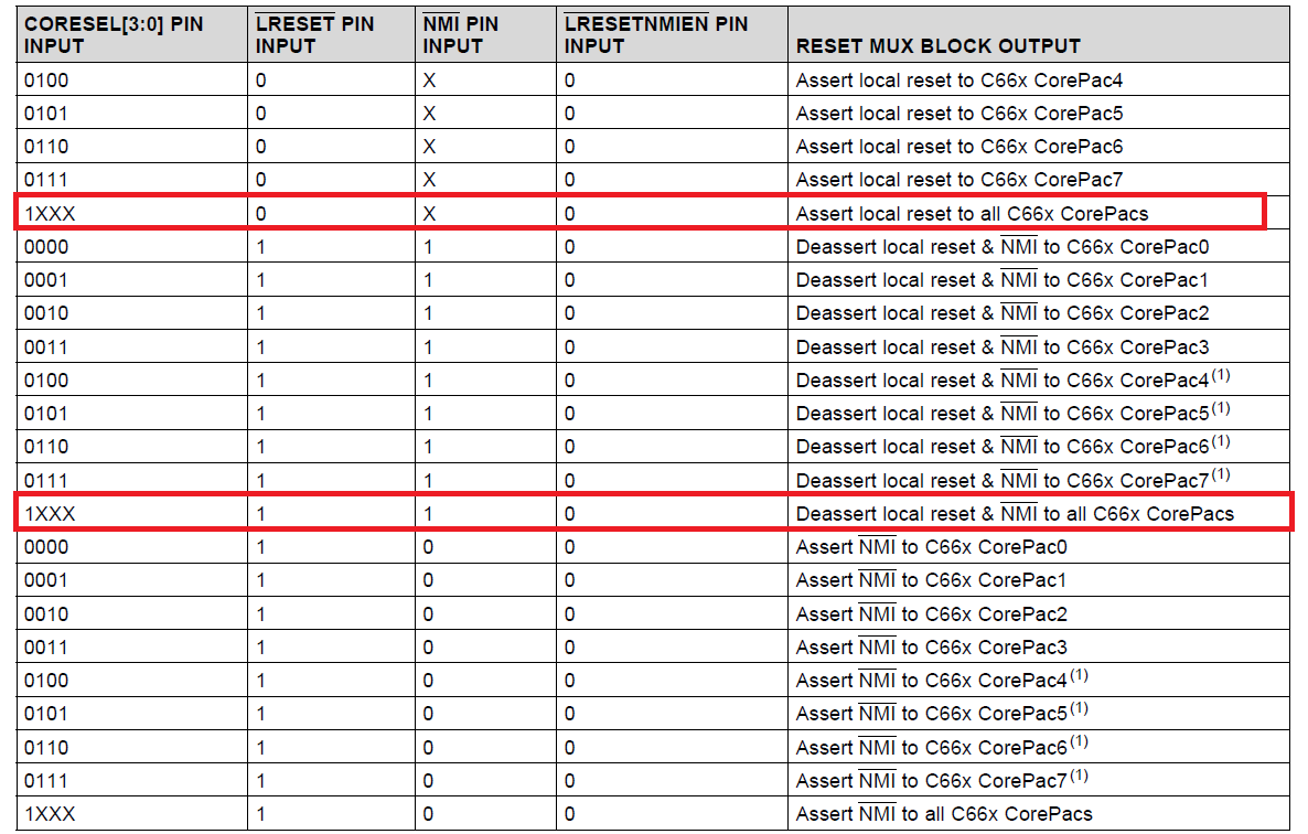
I have a question about the LRESETNMIEN and LRESET behaviour relative to table 8-31 of the SPRS866G datasheet :
(CORESEL() assumed to be static 1XXX.)

The table 8-31 identifies RESET assertion and RESET de-assertion events.

Assuming that the device entered the local reset state by (LRESET,NMI,LRESETNMIEN) = (0,1,0), the table explains that the device then enters the local deassertion state upon the
(LRESET,NMI,LRESETNMIEN) = (1,1,0) event.

In the other hand there is also the figure 11-33 which becomes a little bit confusing because I understand here that the Reset Deassertion is caused the the LRESETNMIEN rising_edge.
Therefore corresponding to the (LRESET,NMI,LRESETNMIEN) = (0,1,1).


Could you clarify please ?

With best regards,
Bruno

  • Hi Bruno,

    Table 8-31 defines the conditions to assert/deassert reset within the device. 66AK2H14 should behave as described in this table.

    Figure 11-33 is a timing diagram that shows when the timing of the reset, lreset and lresetnmien signals (their setup, hold time & pulse width). It complements Table 11-36. NMI and LRESET Timing Requirements (1).

    Best Regards,
    Yordan
  • Hi Yordan,

    I Thank you for the answer even though this does not help me that much.

    I try to explain differently the problem I have :

    IF you look at the table 8-31

    you can notice that the signal LRESETNMIEN is always set to '0' except for first raw.

    Therefore, according to that table we can generate RESET event to the processor only by toggling the LRESET pin to '0' and then resume from RESET by toggling again LRESET pin to '1'

    This is what the table tells us, but this is not coherent with the figure 11-33 which REQUIRES that LRESETNIMEN also reverts back to '1'

    Therefore the question : what is correct ? table ? or figure ?

    With best regards,

    Bruno

  • Bruno,

    Table 8-31 shows the result of the combinatorial logic of the CORESEL[3:0], LRESETz and NMIz pins.  The LRESETNMIENz column is there to show that the event only occurs when it is low.  However, the timing of Figure 11-33 is required.  Therefore, think of the CORESEL[3:0], LRESETz and NMIz pins as async inputs to a decoder.  Then think of LRESETNMIENz as the active signal that is sampled based on the decoder inputs.  The transition of LRESETNMIENz from high to low and then back high (per the timing requirements listed, with the decoder output unchanging) is required.

    Tom

  • OK Tom,
    That becomes perfectly clear.
    Thank's for your help,
    Bruno